Service life sensor device

a sensor device and service life technology, applied in the direction of electrical/magnetic measuring arrangement, solids analysis using sonic/ultrasonic/infrasonic waves, material strength using tensile/compressive forces, etc., can solve the problem of insufficient space occupied by measuring units of this type, the inability to cabling and layout of these units is generally impractical and feasible, and the operation of measuring operations is very labor-intensiv

Active Publication Date: 2007-10-16
THIELE GMBH & CO KG
View PDF13 Cites 0 Cited by
  • Summary
  • Abstract
  • Description
  • Claims
  • Application Information

AI Technical Summary

Benefits of technology

[0012]The service life sensor device of the present invention resolves prior art problems because it is energy self-sufficient and can be remotely operated online. Furthermore, the device according to the present invention requires no complicated cable lay-out and therefore is simple to use on a variety of installations. Measurements can be taken online so that the device is not limited to a specific application and since the data measured from the structural component of the installation is taken directly online, expensive downstream measuring processes are not necessary and the so collected data is already processed by the microcontroller integrated into the sensor module. Due to its small and compact construction, the sensor module can be easily installed almost anywhere on the structural component of the installation with the stress data collected from the structural component already processed within the sensor module. The sensor device has application in a wide-variety of machine-technical installations, such as for example on conveyor chains and other installations that carry static or dynamic loads. All necessary communications in connection with the sensor device are carried out either via a low-frequency (125 kHz) antenna integrated into the sensor module or via a high frequency antenna (2.4 Gigahertz) also integrated into the sensor module.
[0016]The low-frequency-communication channel receives its operating current from the low frequency signal of 125 kHz. That is, the sensor module can be turned on and off without reliance on the sensor module's own current supply.

Problems solved by technology

However, the cabling lay-out of these units is generally impractical and feasible in only few applications to monitor the structural building components and such measuring operations are very labor-intensive.
In addition, measuring units of this type take up an inordinate amount of space due to their complexity in supplying necessary electric current, providing data interpretation units and measuring sensors, such that taking continuous measurements with these monitoring devices are only feasible in a limited number of applications due to the afore-stated constraints.
Therefore, utilization of this type of sensors is generally associated with high expenses and considered impractical in their operation.
The foregoing method of measuring, collecting and determining data is however cumbersome and since the device is operated based on batteries, its operational readiness is dependent on the capacity of the battery.

Method used


Image

  • Service life sensor device
  • Service life sensor device
  • Service life sensor device

Examples


Embodiment Construction

[0028]Throughout all the Figures, same or corresponding elements may generally indicate same reference numerals. These depicted embodiments are to be understood as illustrative of the invention and not as limiting in any way. It should also be understood that the drawings are not necessarily to scale and that the embodiments may be illustrated by graphic symbols, phantom lines, diagrammatic representations and fragmentary views. In certain instances, details which are not necessary for an understanding of the present invention or which render other details difficult to perceive may have been omitted.

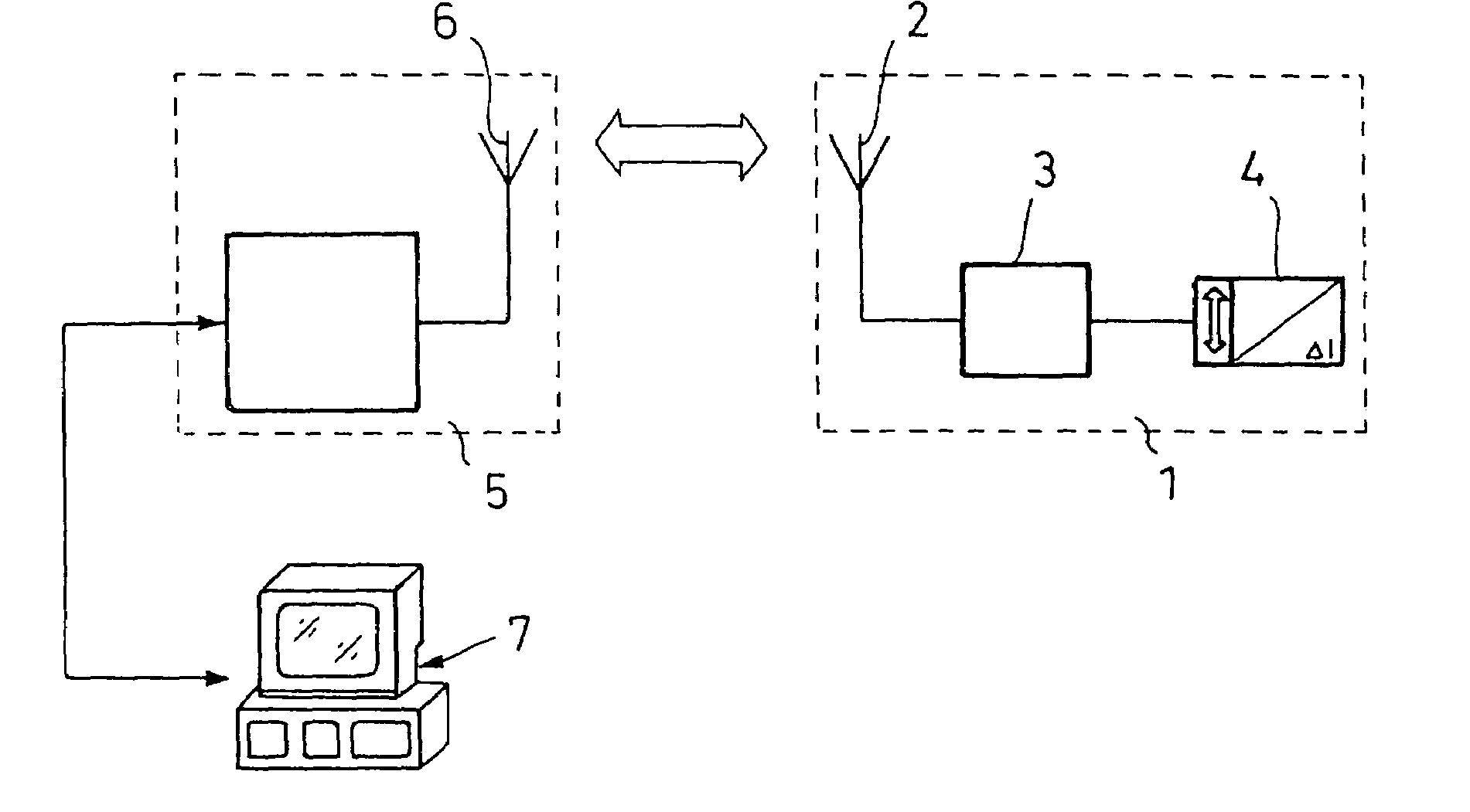
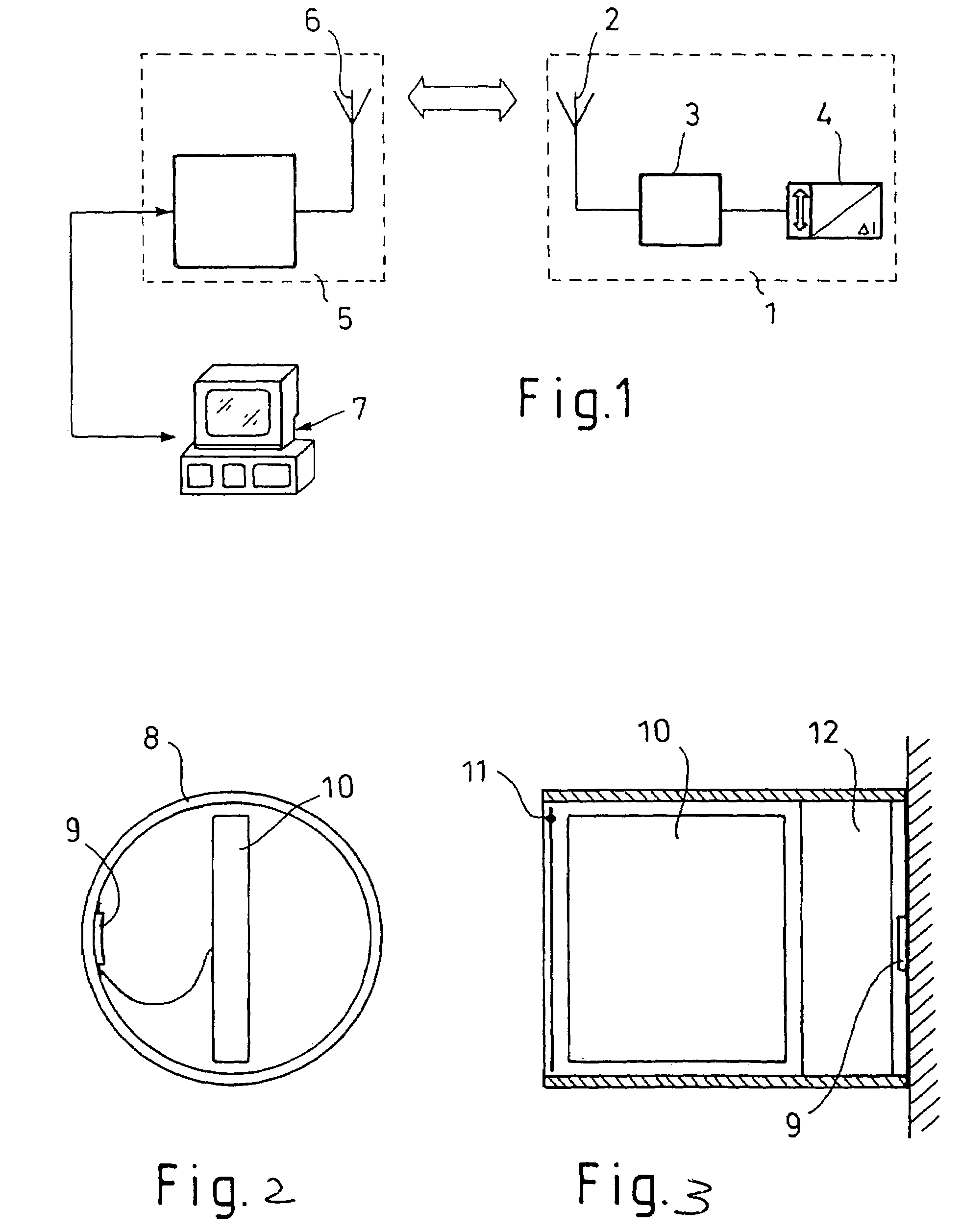
[0029]Turning now to the drawing, and in particular to FIG. 1, there is shown in a schematic illustration, the service life sensor device according to the present invention in its principally simple form in which the device includes essentially 3 units. The sensor module 1 includes a coupling element in the form of an antenna 2, a processing unit 3 and a sensor element 4 for disposition ...


PUM

PropertyMeasurementUnit
frequencyaaaaaaaaaa
frequencyaaaaaaaaaa
frequencyaaaaaaaaaa

Abstract

A device for monitoring the service life of a machine-technical installation includes a sensor module and at least a measuring sensor for detecting stresses and expansions from a structural component of the machine-technical installation, a microcontroller, an antenna arrangement and a current source; the sensor module being in bi-directional connection with a data processing unit and having an antenna arrangement integrated therein, the antenna arrangement including a low-frequency antenna by means of which the sensor module is turned on and off and a high-frequency antenna for sending and receiving high frequency signals and wherein the sensor module can transition from an operating mode into a stand-by mode for energy efficiency and is reactivated through a signal from a detector element.

Description

CROSS-REFERENCES TO RELATED APPLICATIONS[0001]This application is a continuation-in-part of prior filed PCT International application no. PCT / DE2004 / 000606, filed Mar. 24, 2004, which designated the United States and on which priority is claimed under 35 U.S.C. §120, the disclosure of which is hereby incorporated by reference, and which claims the priorities of German Patent Applications, Serial Nos. 103 13 726.2, filed Mar. 27, 2003, and 103 52 959.4, filed Nov. 13, 2003, pursuant to 35 U.S.C. 119(a)-(d), the disclosure of which is incorporated herein by reference.[0002]This application also claims the priority of German Patent Application, Serial No. 10 2004 040 407.0, filed Aug. 19, 2004, pursuant to 35 U.S.C. 119(a)-(d), the disclosure of which is incorporated herein by reference.BACKGROUND OF THE INVENTION[0003]The present invention relates to a service life sensor device for determining the material stress in machine-technical installations, and in particular, a service life s...

Claims


Application Information

Patent Timeline
Patent Type & Authority Patents(United States)
IPC IPC(8): G01B5/30G01L5/04G01L5/10
CPCG01B5/30G01L5/102G01L5/047
Inventor NIENHAUS, KARL
Owner THIELE GMBH & CO KG
Why Eureka
Try Eureka