Pivotable suspension element

a suspension element and pivoting technology, applied in resilient suspensions, ceilings, internal osteosynthesis, etc., can solve the problem of relatively high product cos

Active Publication Date: 2007-10-16
ACCESS TECH
View PDF12 Cites 38 Cited by
  • Summary
  • Abstract
  • Description
  • Claims
  • Application Information

AI Technical Summary

Benefits of technology

[0005]The present invention seeks to provide a pivotable suspension element in which at least some of the aforedescribed problems are mitigated or overcome.

Problems solved by technology

Additionally, the number of component parts required to construct the pivotable suspension elements of the aforedescribed type, and the associated assembly time in manufacture results in the product being relatively expensive.

Method used


Image

  • Pivotable suspension element
  • Pivotable suspension element
  • Pivotable suspension element

Examples


Embodiment Construction

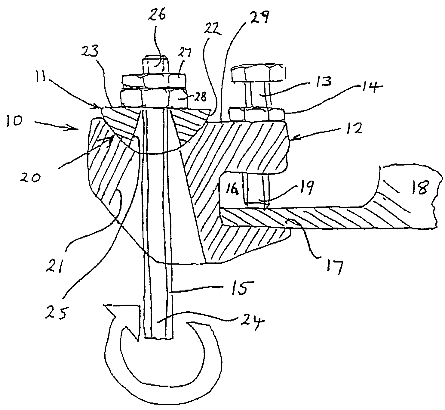
[0027]The pivotable suspension element 10 comprises a support member 11 in the form of a hemispherical washer, a body formation 12, a bolt 13 and lock nut 14 which acts as clamp means. The element 10 is shown in combination with an elongate suspension rod 15. The body 12 is of an integral construction formed by casting or moulding of metal or plastics material. The body 12 defines a slot formation 16 into which the edge region of a flange 17 of a support I beam 18 may be located. The clamp bolt 13 extends through a through-bore provided in the body 12 at a position aligned with the slot 16 whereby the distal end 19 of the bolt may be brought into firm, clamping contact with the flange 17 to hold the flange firmly in the slot 16. The lock nut 14 is provided to ensure that the bolt 13 is retained in position.

[0028]The body 12 comprises a part-spherical concave bearing seat surface 20, and a through-bore 21 of a frusto-conical shape extends through the body, increasing in cross-section...


PUM


Abstract

A pivotable suspension element includes a support member having a part-spherical bearing surface clamp element and a body portion, the body portion having an integral formation of a slot to receive a part of a component to which the pivotable suspension element may be secured; a locator formation for the clamp element whereby, in use, the clamp element may be operated to clamp a flange in the slot; a part-spherical seat, and a through-passage extending through the body from the part-spherical seat, wherein the curvature of the part-spherical seat of the body portion corresponds substantially with that of the bearing surface of the support member and wherein the cross-sectional size of the through-passage increases in a direction away from the part-spherical seat.

Description

BACKGROUND OF THE INVENTION[0001]This invention relates to a pivotable suspension element and in particular, though not exclusively, to a pivotable suspension element suitable for securing to a supporting flange, such as a flange of an I beam girder and to allow a component to be pivotally supported relative to the supporting flange.[0002]Many types of pivotable suspension elements are known and examples are to be found in, for example, the publications of EP 677689A and EP 1165995A. These types of pivotable suspension elements have in common the provision of a hinge pin to allow, in use, for relative pivotal movement of two components inter-connected by the pivotable suspension element.[0003]Although said known types of pivotable suspension elements have been employed for many years, and have been the subject of many modifications and improvements, the designs have always needed to ensure that the hinge pin is held securely, that the shear strength of the pin and pin support is ade...

Claims


Application Information

Patent Timeline
Patent Type & Authority Patents(United States)
IPC IPC(8): E04G3/00B60K17/00
CPCF16B2/065Y10T403/7117Y10T403/645Y10T403/32704Y10T403/32696F16B2200/506
Inventor JORDAN, MATTHEW EDWARD
Owner ACCESS TECH
Why Eureka
Try Eureka