Damping apparatus for moving furniture parts

Inactive Publication Date: 2007-10-16
ARTURO SALICE
View PDF22 Cites 22 Cited by
  • Summary
  • Abstract
  • Description
  • Claims
  • Application Information

AI Technical Summary

Benefits of technology

[0020]It is particularly advantageous for the first damping stage to exert a lower damping action than the second damping stage. Provision can be made for the second damping stage to be designed such that its starting fricti

Problems solved by technology

The design of the damping apparatus with telescopic cylinders re

Method used


Image

  • Damping apparatus for moving furniture parts
  • Damping apparatus for moving furniture parts
  • Damping apparatus for moving furniture parts

Examples


Embodiment Construction

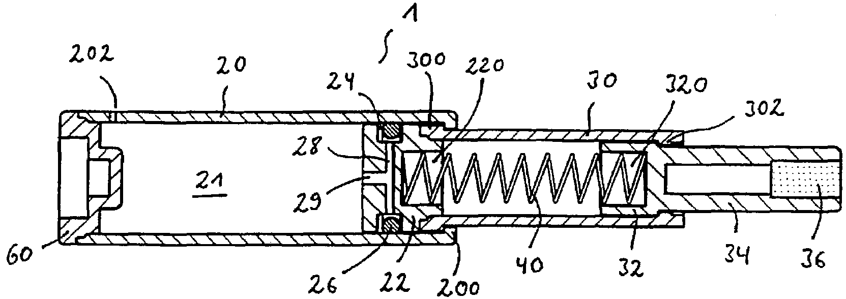
[0026]A damping apparatus 1 in accordance with the invention can be seen from FIG. 1. This consists of two damping stages of which the first has the cylinder 30 having the piston 32 and the second has the cylinder 20 having the piston 22.

[0027]The piston 32 is guided in a longitudinally displaceable manner in the cylinder 30 of the first damping stage. The piston 32 has a plunger 34 in one piece with it in whose end region the magnet 36 is arranged.

[0028]The cylinder 30 has in its end region the piston 22 of the second damping stage, said piston 22 being fixedly connected to said cylinder 30. The connection can take place, for example, by ultrasonic welding.

[0029]The piston 22 is displaceably guided in the cylinder 20 of the second damping stage.

[0030]The piston 32 has the cut-out 320 an the piston 22 has the cut-out 220 in which the end regions of the spring 40 of the first damping stage are received.

[0031]The piston 32 is supported in its starting position shown in FIG. 1 at the a...


PUM


Abstract

The present invention relates to a damping apparatus for moving furniture parts, for example doors, flaps or drawers. Such a damping apparatus of a compact construction which avoids a possible springing back movement of the furniture parts is provided in accordance with the invention in that the damping apparatus has at least two damping stages each having a cylinder having a piston longitudinally displaceable therein which exert a damping action of different strengths.

Description

BACKGROUND OF THE INVENTION[0001]The present invention relates to a damping apparatus for moving furniture parts, for example for doors, flaps or drawers.[0002]Such damping apparatuses are known in numerous different embodiments. DE 44 09 716 A1 shows an air damper which consists of a piston and a cylinder and whose piston is braked on its plunging into the cylinder by the compressed air in the cylinder, with the escape of the air being largely prevented by a seal through which the piston is moved on plunging into the cylinder. DE 37 29 597 A1 likewise shows a damping apparatus comprising a cylinder and a piston longitudinally displaceably received therein. A spigot is received in the cylinder which has a diameter changing in the longitudinal direction and which is guided in the piston designed as a hollow piston. The air compressed in the cylinder on the insertion of the piston is expanded depending on the position of the piston by the annular gap between the spigot and the bore of...

Claims


Application Information

Patent Timeline
IPC IPC(8): F16F9/18E05F5/02E05F5/08E05F5/10F16F9/02F16F9/32F16F9/48
CPCE05F5/08E05F5/10F16F9/0209E05F5/02A47B2210/0094E05Y2800/22E05Y2201/21E05Y2201/212E05Y2201/218E05Y2201/256E05Y2201/264E05Y2201/46E05Y2201/474E05Y2800/244E05Y2900/20A47B96/00
Inventor SALICE, LUCIANO
Owner ARTURO SALICE
Why Eureka
Try Eureka