
Damping spring for use in agricultural implements

a technology for agricultural implements and springs, applied in the field of damping springs for the motion of rake wheels, can solve the problems of loss of production, repeated structural stress on the wheel rake, and inability to absorb shock, etc., and achieve the effect of increasing damping, adjusting the damping degree, and expanding more readily

Active Publication Date: 2008-01-29
H & S MFG
View PDF15 Cites 5 Cited by
  • Summary
  • Abstract
  • Description
  • Claims
  • Application Information

AI Technical Summary

Benefits of technology

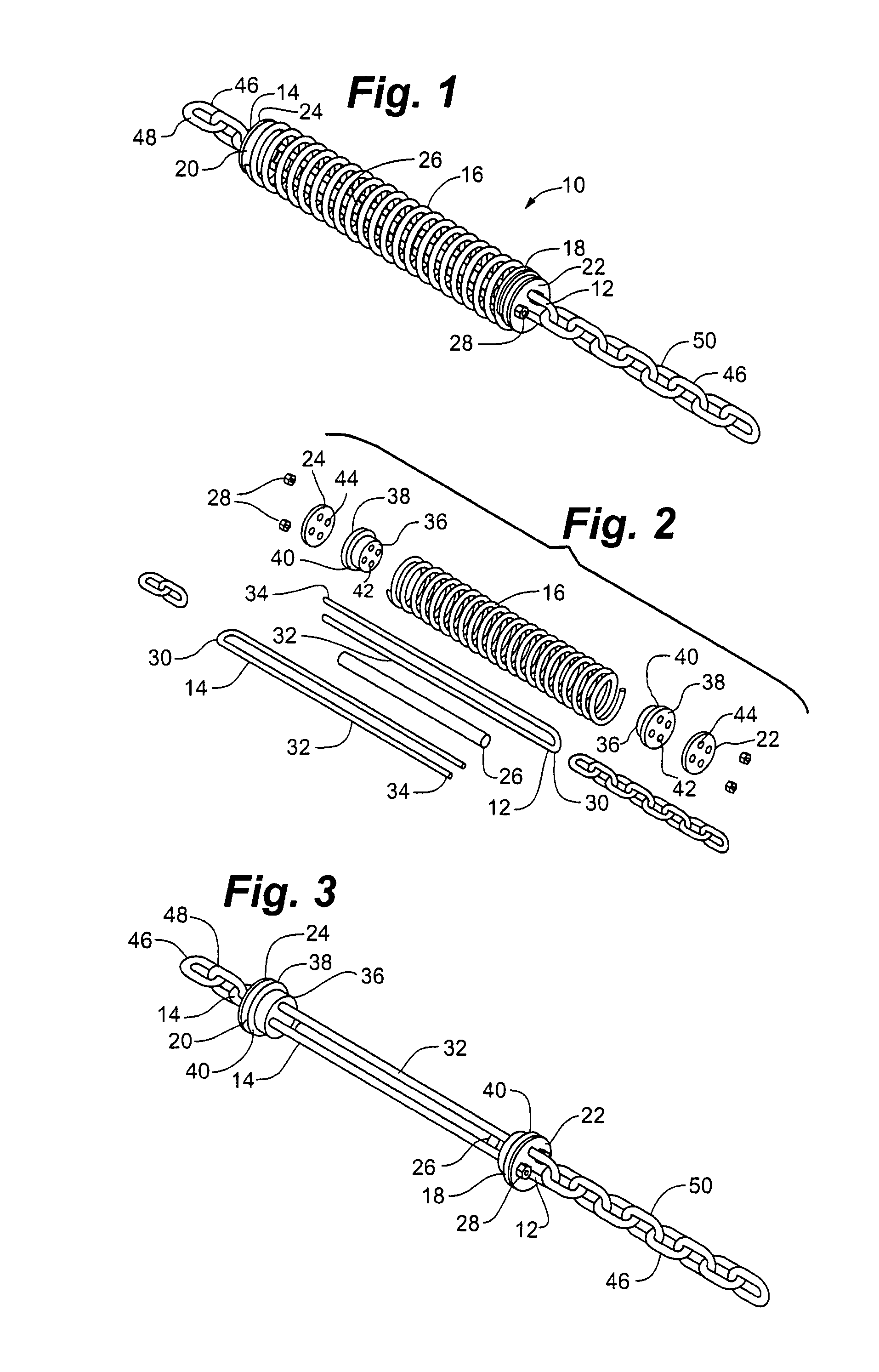
[0023]As tension on the U-shaped ends of the two extended U-bolts is relieved, the coil compression spring tends to return to its extended length. As this occurs, the two extended U-bolts move in opposite directions while rubbing against the sides of the resilient damping rod. Thus, the resilient damping rod will slow the motion of the two extended U-bolts as they pass by each other and damp the action of the coil compression spring as it returns to its extended length. In addition, as the extended U-bolts may be forced into a bowed or flexed position by expansion of the resilient damping rod, friction occurs between the two extended U-bolts and the spring holders where the U-bolts pass through the opposed holes in the spring holders. This also contributes to the damping action of the resilient damping rod.
[0024]The degree of damping can be adjusted by adjusting the length of the resilient damping rod. A longer resilient damping rod will expand more readily as the coil compression spring is compressed, thus increasing damping. A shorter resilient damping rod will reduce damping because the resilient damping rod will not be compressed until the compression coil spring is further compressed by the motion of the two extended U-bolts.

Problems solved by technology

Exposing the cut hay to sunlight longer than is required to adequately dry it, however, can result in unacceptable loss of nutritive value of the hay due to deterioration of the protein level.
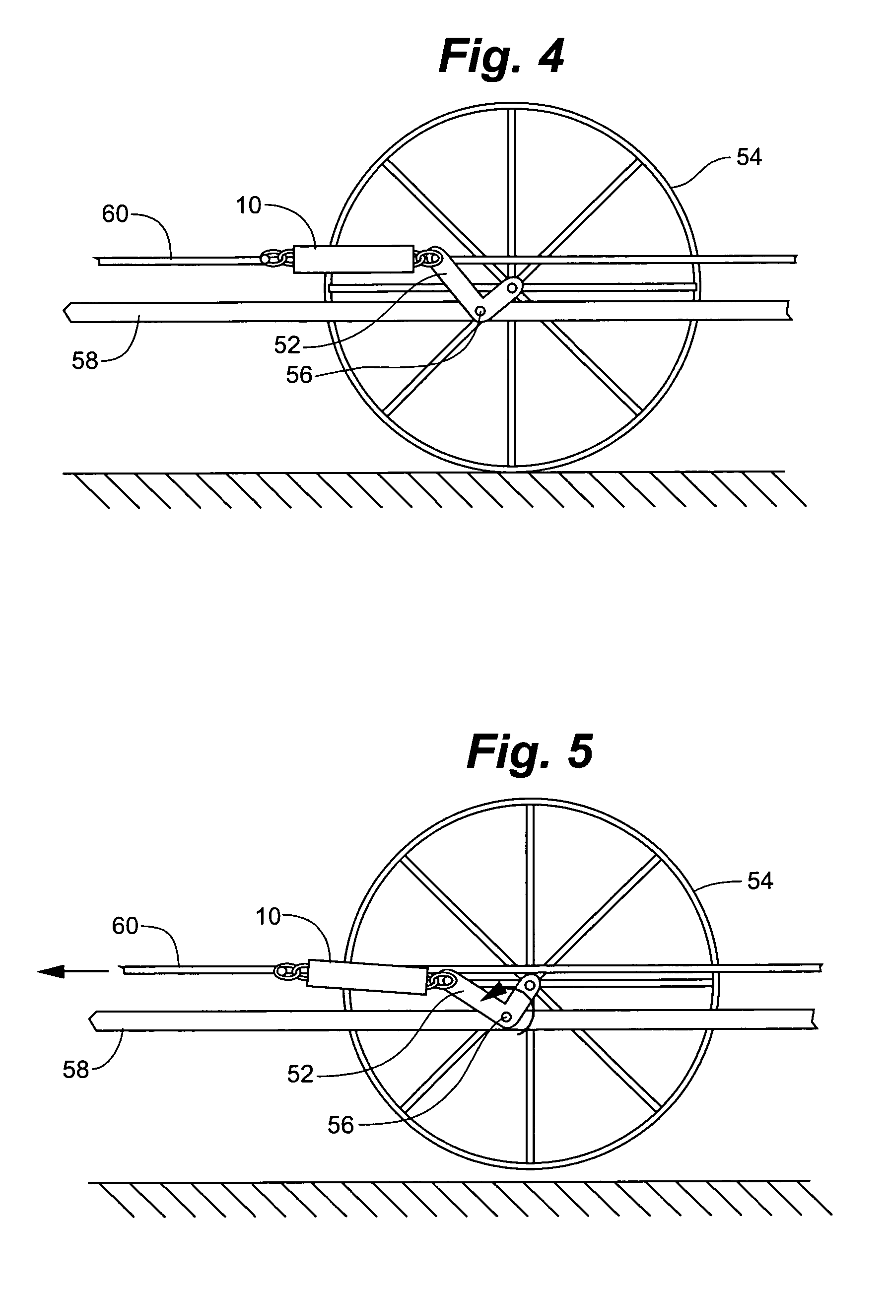
Wheel rakes are subject to repeated structural stresses due to uneven ground and irregular distribution of forage material when propelled through fields of cut hay to form the hay into windrows.
Compacted, damp or unusually heavy forage can create problems in that the rake wheels may tend to roll over or skip over areas of heavy compacted forage rather than lifting it and raking it toward the desired windrow.
If this occurs, loss of production and increased costs result.
Loss of production occurs if forage is left in the fields to decay rather than being harvested.
Increased costs can occur if it is necessary to pass through the fields several times to accomplish sufficient raking to gather all of the forage desired.
If wheel float is too light, wheels will pass over the crop and leave some of the crop unraked.
If wheel float is too heavy, wear on the rake wheels is increased and the rake wheel will dislodge more soil and rocks from the earth and increase contamination of the hay.
Several problems arise with this arrangement.
With repeated stress the spring eyes may suffer metal fatigue and break.
This not only interferes with proper raking action but also may cause damage to the rake wheel and cause loss of the spring in the field where it may later cause damage to other farm implements or equipment.
For example, a lost spring may interfere with a hay mower during the next mowing of the field and damage the hay mower.
Tension springs may also be damaged by being overextended.
This will cause the rake wheel to bear on the ground to a greater degree than it should and may cause excess wear and or damage.
Further, the tension spring supporting the rake wheel may “snap back” when the spring is loaded and then the load on the tension spring is abruptly released.
This can also damage the rake wheel assembly.

Method used


Image

  • Damping spring for use in agricultural implements
  • Damping spring for use in agricultural implements
  • Damping spring for use in agricultural implements

Examples


Embodiment Construction

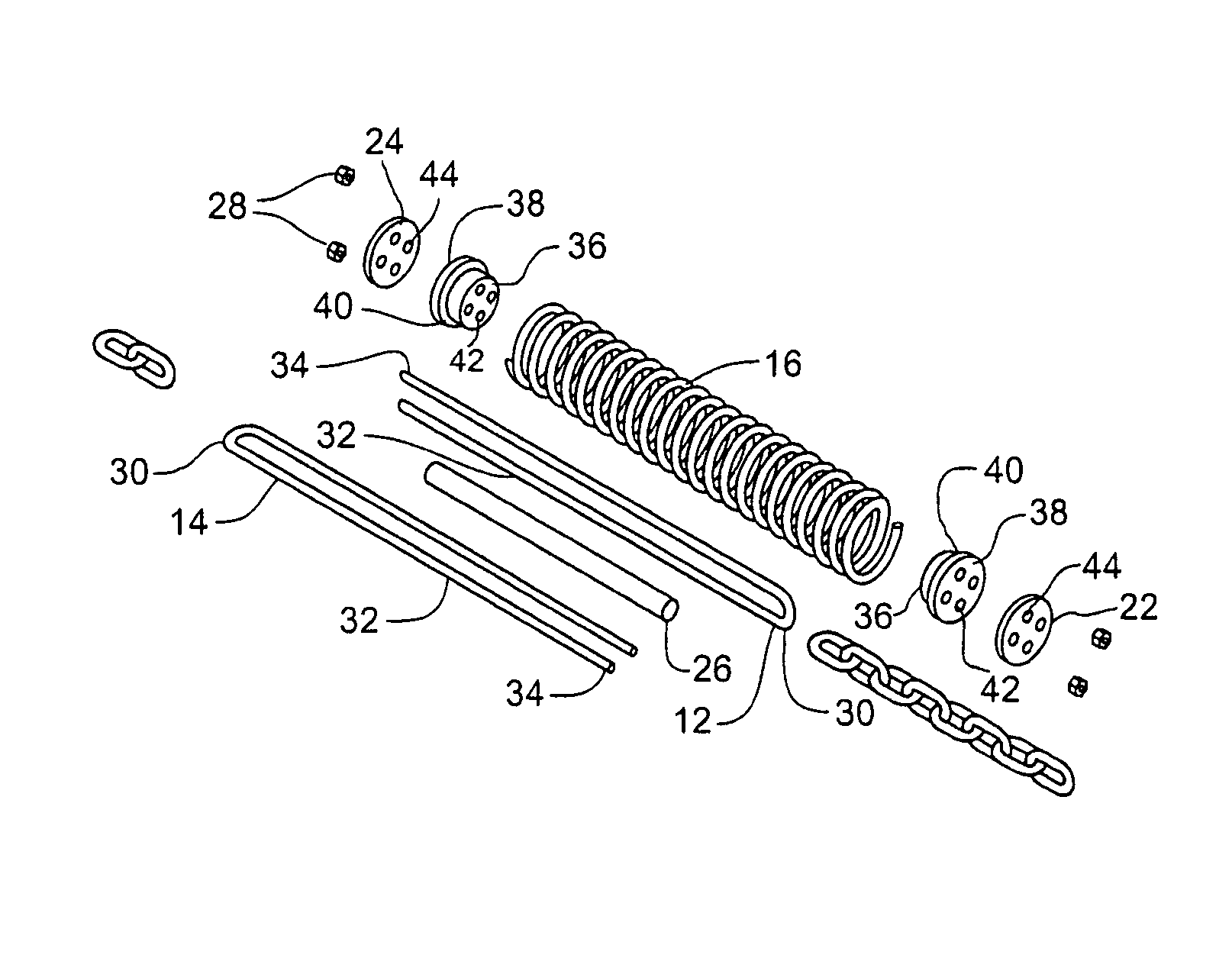
[0041]Referring to FIGS. 1-3, damping spring 10 of the present invention generally includes first extended U-bolt 12, second extended U-bolt 14, coil compression spring 16, first spring holder bushing 18, second spring holder bushing 20, first spring holder washer 22, second spring holder washer 24, resilient damping member 26, and nuts 28. First extended U-bolt 12 and second extended U-bolt 14 are substantially similar and include U-shaped ends 30, extended shafts 32 and threaded ends 34. First extended U-bolt 12 and second extended U-bolt 14 may be formed from stainless steel or other high strength, corrosion resistant material.

[0042]Coil compression spring 16 is a generally conventional compression spring of a size appropriate to contain first extended U-bolt 12 and second extended U-bolt 14 within its inner diameter.

[0043]First spring holder bushing 18 and second spring holder bushing 20 are substantially similar in construction. First spring holder bushing 18 and second spring ...


PUM


Abstract

A damping spring assembly particularly but not exclusively useful for damping the motion of rake wheels in agricultural wheel rakes. The damping spring includes a pair of extended U-bolts and a coil compression spring. The extended U-bolts are connected to spring holder bushings which bear on the ends of the coil compression spring. As the coil compression spring is compressed, a constrained resilient damping rod located within the extended shafts of the extended U-bolts is likewise compressed in length and expands in diameter to bear against the extended shafts of the extended U-bolts, thus providing a damping action to prevent snapping back of the damping spring.

Description

RELATED APPLICATION[0001]The present application claims the benefit of U.S. Provisional Application No. 60 / 607,813 filed Sep. 8, 2004, which is incorporated herein in its entirety by reference.FIELD OF THE INVENTION[0002]The invention relates to agricultural implements and more particularly to springs for damping of the motion of rake wheels used in wheel rakes that are useful to form windrows from cut forage.BACKGROUND OF THE INVENTION[0003]A primary goal in the harvesting of hay or forage is to dry the hay as soon as possible and then to remove it from direct exposure to sunlight. The hay must be dried before storage to avoid the problems of mold and spontaneous combustion. Exposing the cut hay to sunlight longer than is required to adequately dry it, however, can result in unacceptable loss of nutritive value of the hay due to deterioration of the protein level.[0004]Typically, hay is harvested into approximately five-foot swaths along the ground, and is exposed to sunlight for t...

Claims


Application Information

Patent Timeline
Patent Type & Authority Patents(United States)
IPC IPC(8): F16F1/00F16F9/00
CPCA01D78/14
Inventor PEETERS, KENNETH J.
Owner H & S MFG
Learn More