Frequency management apparatus, systems, and methods

a frequency management and frequency management technology, applied in the field of circuits, can solve the problems of increasing power consumption and core temperature, supply voltage “drooping” (downward changes), and circuit delays within the microprocessor may increas

Active Publication Date: 2007-10-16
TAHOE RES LTD
View PDF16 Cites 34 Cited by
  • Summary
  • Abstract
  • Description
  • Claims
  • Application Information

AI Technical Summary

Problems solved by technology

Relatively higher levels of activity may be associated with computationally-intensive tasks, may increase power consumption and core temperature, and may result in supply voltage “droops” (downward changes).
Circuit delays within the microprocessor may increase as the core temperature increases and the operational voltage decreases.
On the other hand, some applications may use only modest amounts of available microprocessor capacity.

Method used


Image

  • Frequency management apparatus, systems, and methods
  • Frequency management apparatus, systems, and methods
  • Frequency management apparatus, systems, and methods

Examples


Embodiment Construction

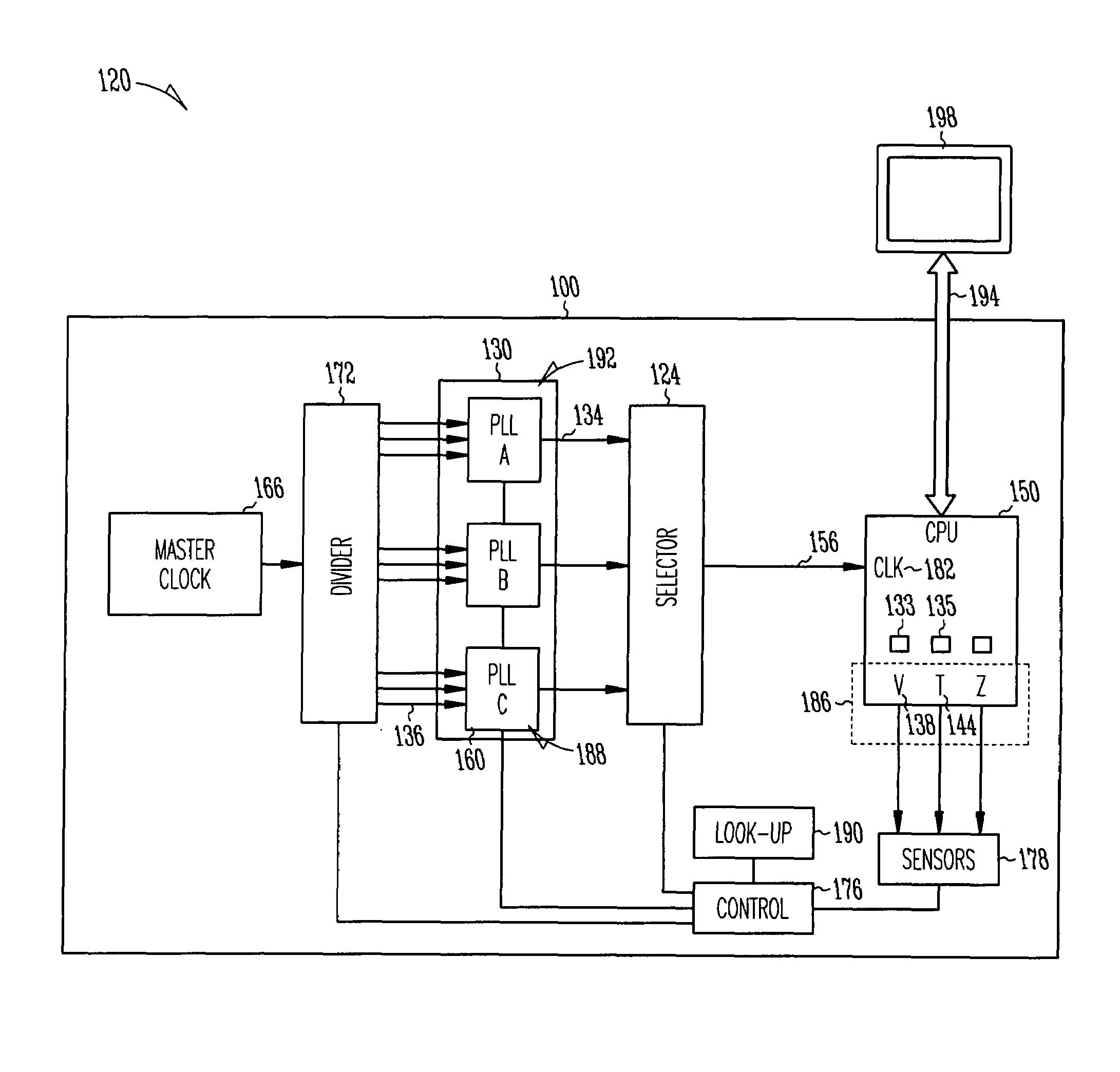
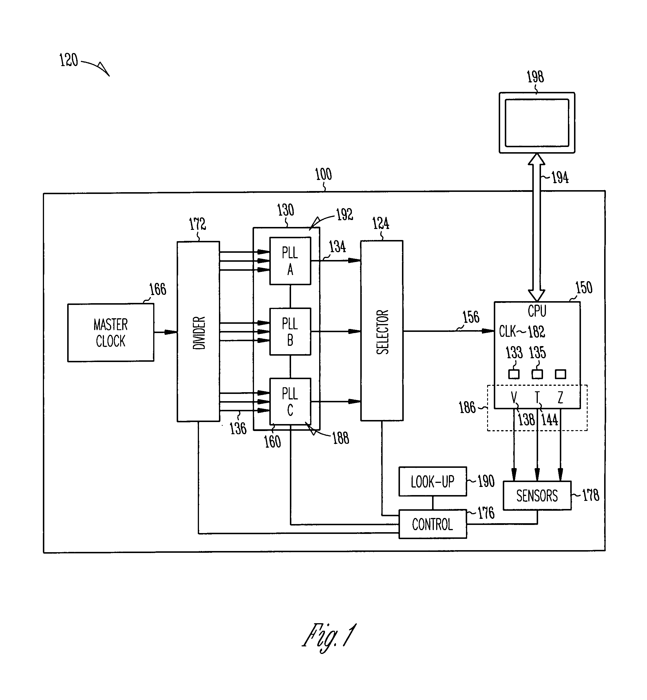
[0007]Various embodiments disclosed herein may enable adjusting a microprocessor frequency of operation according to sensed operational parameters including, without limitation, temperature and / or operational voltage. In some embodiments, a phase-locked loop (PLL) may provide a variable rate clock.

[0008]Several mechanisms may be used to implement clock variability. For example, a microprocessor may experience operational voltage droops with time constants on the order of about 10-1000 nanoseconds. A PLL capable of re-locking within such a short time may not be widely available. In addition, undershot / overshoot of the PLL during re-lock may cause operational errors.

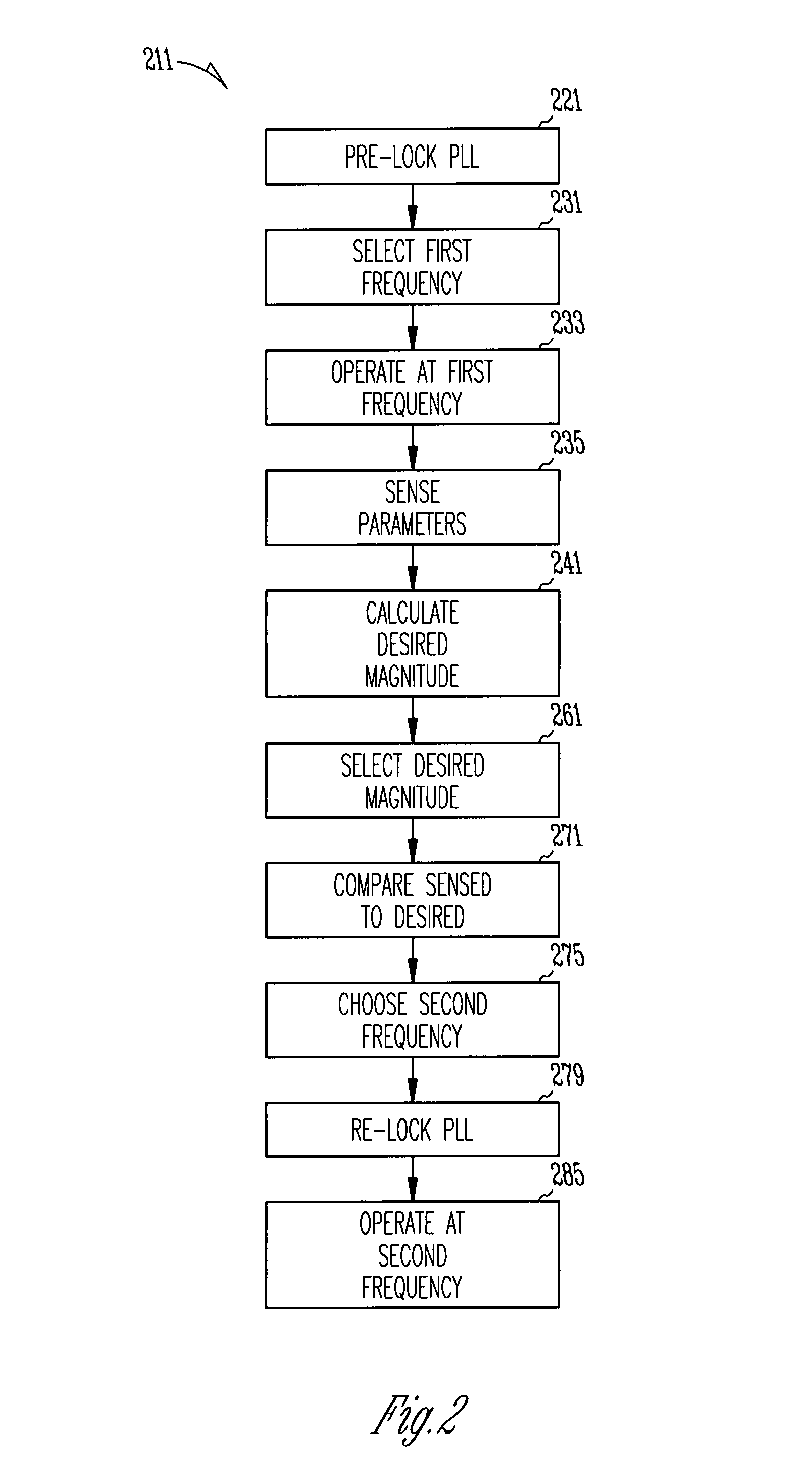
[0009]Therefore, some embodiments disclosed herein may utilize multiple PLLs as a bank of available clocks. Any number of PLLs in the bank may be pre-locked to a frequency anticipated for possible future use. Microprocessor clock frequency changes may then be accomplished by selecting a PLL pre-locked to the required frequ...


PUM


Abstract

Apparatus and systems, as well as methods and articles, may operate to select a microprocessor clock frequency responsive to a desired voltage and / or a desired temperature of operation.

Description

TECHNICAL FIELD[0001]Various embodiments described herein relate to circuits generally, including apparatus, systems, and methods used to clock such circuits.BACKGROUND INFORMATION[0002]During the operation of a microprocessor, operational parameters such as core temperature, voltage of operation, and power consumption may vary according to activity within the microprocessor. Relatively higher levels of activity may be associated with computationally-intensive tasks, may increase power consumption and core temperature, and may result in supply voltage “droops” (downward changes). Circuit delays within the microprocessor may increase as the core temperature increases and the operational voltage decreases.[0003]On the other hand, some applications may use only modest amounts of available microprocessor capacity. Thus, a conservatively clocked microprocessor may be capable of reliable operation at a higher frequency.BRIEF DESCRIPTION OF THE DRAWINGS[0004]FIG. 1 comprises a diagram of a...

Claims


Application Information

Patent Timeline
Patent Type & Authority Patents(United States)
IPC IPC(8): H03K17/00
CPCG06F1/06G06F1/206G06F1/324G06F1/3203Y02B60/1217Y02D10/00
Inventor NARENDRA, SIVA G.TSCHANZ, JAMES W.DE, VIVEK K.KURD, NASSER A.BARKATULLAH, JAVED
Owner TAHOE RES LTD
Why Eureka
Try Eureka