Multilayer capacitor

a multi-layer capacitor and capacitor technology, applied in the field of multi-layer capacitors, can solve the problems of difficult control of equivalent series resistance, the demand for increasing the equivalent series resistance, and the contradictory nature of the demand for increasing the capacity of the multi-layer capacitor, so as to reduce the equivalent series inductance, regulate the equivalent series resistance easily, and facilitate the effect of mounting the multi-layer capacitor to the substra

Active Publication Date: 2007-10-16
TDK CORPARATION
View PDF9 Cites 14 Cited by
  • Summary
  • Abstract
  • Description
  • Claims
  • Application Information

AI Technical Summary

Benefits of technology

[0008]For overcoming the above-mentioned problem, it is an object of the present invention to provide a multilayer capacitor which can regulate the equivalent series resistance easily with a high precision.
[0022]The present invention can provide a multilayer capacitor which can regulate the equivalent series resistance easily with a high precision.

Problems solved by technology

However, the following problem exists when adjusting the multilayer capacitor equipped with a terminal conductor having a multilayer structure including an inner resistance layer to a desirable value.
Namely, for adjusting the equivalent series resistance to a desirable value in a multilayer capacitor equipped with a terminal conductor having a multilayer structure including an inner resistance layer, the thickness and material composition of the inner resistance layer included in the terminal conductor must be regulated while remaining independent of the capacitor's capacitance and ESL, which makes it very difficult to control the equivalent series resistance.
Thus, the demand for increasing the capacity of the multilayer capacitor and the demand for increasing the equivalent series resistance contradict each other.

Method used


Image

  • Multilayer capacitor
  • Multilayer capacitor
  • Multilayer capacitor

Examples


first embodiment

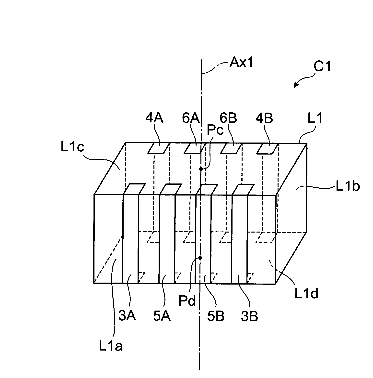
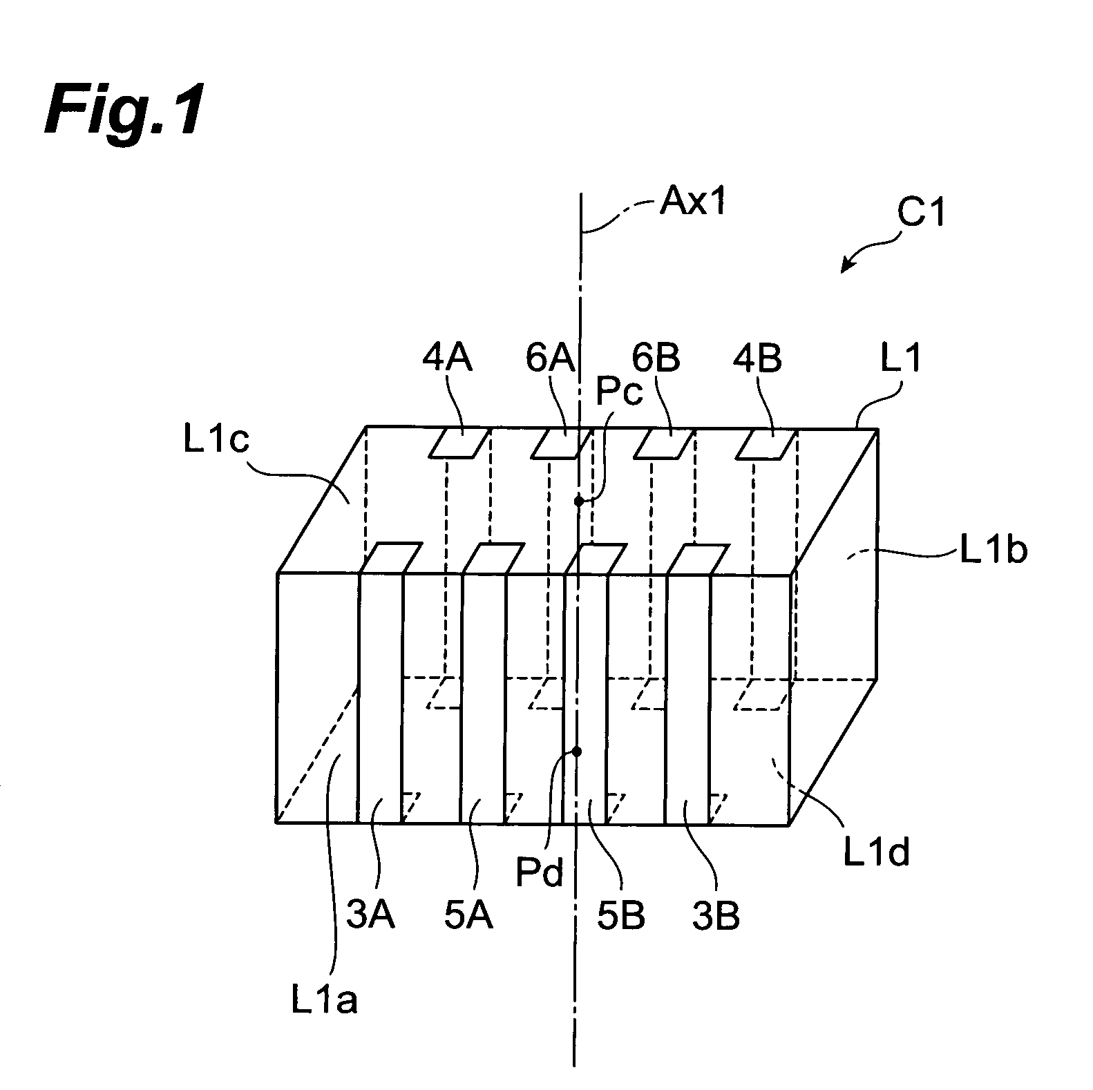
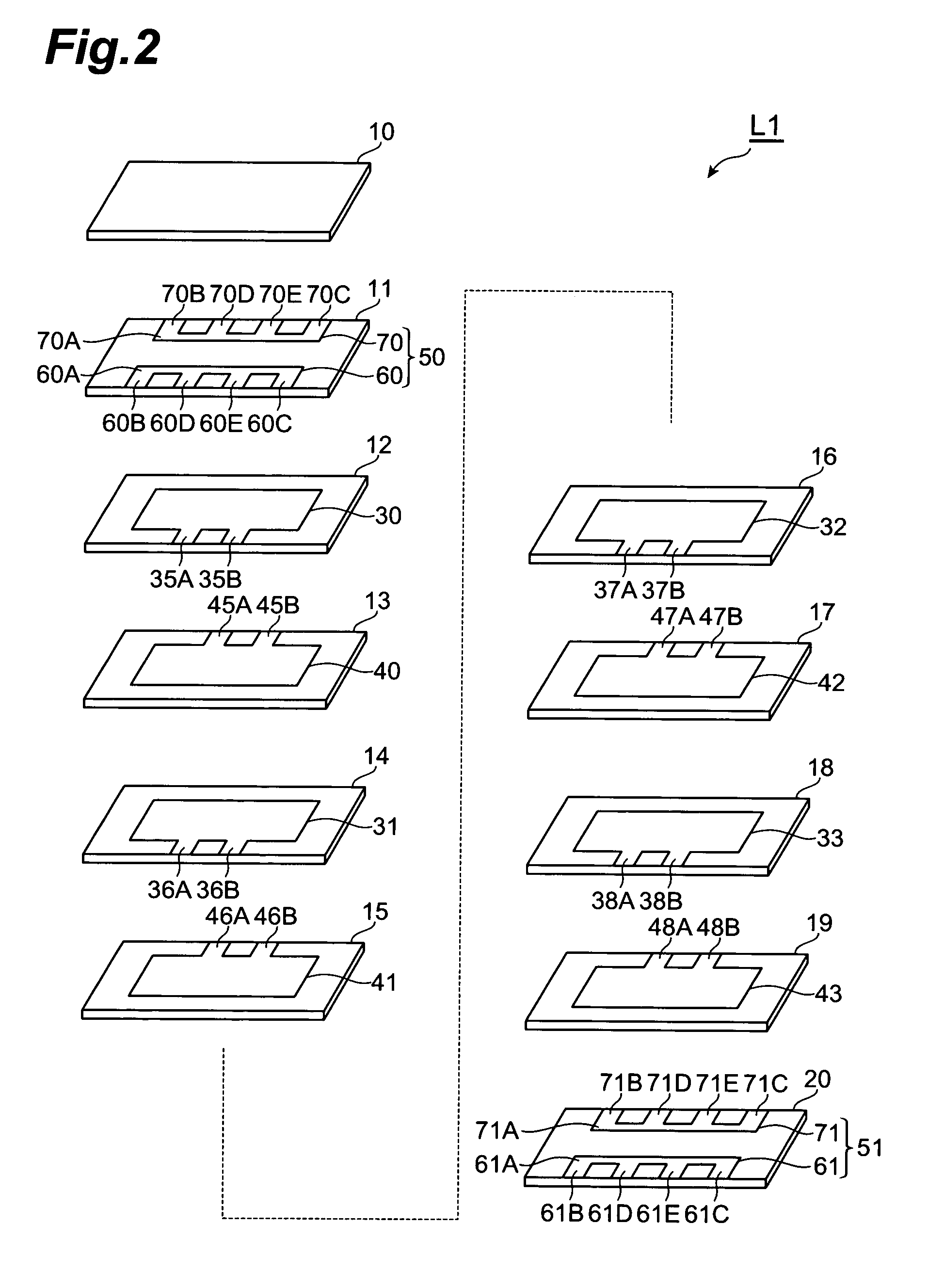
[0048]With reference to FIGS. 1 and 2, the structure of the multilayer capacitor C1 in accordance with a first embodiment will be explained. FIG. 1 is a perspective view showing the multilayer capacitor in accordance with the first embodiment. FIG. 2 is an exploded perspective view of the multilayer body included in the multilayer capacitor in accordance with the first embodiment.

[0049]As shown in FIG. 1, the multilayer capacitor C1 comprises a multilayer body L1 having a substantially rectangular parallelepiped form and a plurality of outer conductors formed on side faces of the multilayer body L1. The plurality of outer conductors include a plurality of (2 in this embodiment) first terminal conductors 3A, 3B, a plurality of (2 in this embodiment) second terminal conductors 4A, 4B, a plurality of (2 in this embodiment) first outer connecting conductors 5A, 5B, and a plurality of (2 in this embodiment) outer connecting conductors 6A, 6B. The plurality of outer conductors are formed ...

second embodiment

[0092]With reference to FIG. 4, the configuration of the multilayer capacitor in accordance with a second embodiment will be explained. The multilayer capacitor in accordance with the second embodiment differs from the multilayer capacitor C1 in accordance with the first embodiment in terms of positions of the inner connecting conductor layers 50, 51 in the laminating direction. FIG. 4 is an exploded perspective view of the multilayer body included in the multilayer capacitor in accordance with the second embodiment.

[0093]As with the multilayer capacitor C1, the multilayer capacitor in accordance with the second embodiment comprises a multilayer body, first terminal conductors 3A, 3B formed on the multilayer body, second terminal conductors 4A, 4B similarly formed on the multilayer body, first outer connecting conductors 5A, 5B similarly formed on the multilayer body, and second outer connecting conductors 6A, 6B similarly formed on the multilayer body, though they are not depicted....

third embodiment

[0107]The configuration of the multilayer capacitor in accordance with a third embodiment will be explained with reference to FIG. 5. The multilayer capacitor in accordance with the third embodiment differs from the multilayer capacitor C1 in accordance with the first embodiment in terms of positions of the inner connecting conductor layers 50, 51 in the laminating direction. FIG. 5 is an exploded perspective view of the multilayer body included in the multilayer capacitor in accordance with the third embodiment.

[0108]As with the multilayer capacitor C1 in accordance with the first embodiment, the multilayer capacitor in accordance with the third embodiment comprises a multilayer body, first terminal conductors 3A, 3B formed on the multilayer body, second terminal conductors 4A, 4B similarly formed on the multilayer body, first outer connecting conductors 5A, 5B similarly formed on the multilayer body, and second outer connecting conductors 6A, 6B similarly formed on the multilayer ...


PUM


Abstract

A multilayer capacitor comprises a multilayer body in which a plurality of dielectric layers and a plurality of first and second inner electrodes are alternately laminated, and a plurality of outer conductors (first and second terminal conductors, and first and second outer connecting conductors) formed on the multilayer body. Each of the outer conductors is formed on one of two side faces of the multilayer body opposing each other. Each of the first and second inner electrodes is electrically connected to the corresponding outer connecting conductor. At least one inner connecting conductor layer including a first and a second inner connecting conductors is laminated in the multilayer body. Each of the inner connecting conductors is electrically connected to the corresponding terminal and outer connecting conductors. The equivalent series resistance of the multilayer capacitor is set to a desirable value by adjusting the number or position of inner connecting conductor layer.

Description

BACKGROUND OF THE INVENTION[0001]1. Field of the Invention[0002]The present invention relates to a multilayer capacitor.[0003]2. Related Background Art[0004]Known as this kind of multilayer capacitor is one comprising a multilayer body in which a plurality of dielectric layers and a plurality of inner electrodes are alternately laminated, and a plurality of terminal conductors formed on the multilayer body.[0005]Power supplies for central processing units (CPUs) mounted in digital electronic devices have been increasing their load current and load transients while lowering their voltage. Therefore, it has become very difficult to suppress the fluctuation in power supply voltage under a tolerable level in response to a drastic change in load current, whereby a multilayer capacitor known as decoupling capacitor has come into use so as to be connected to a power supply. At the time when the load current fluctuates transiently, the multilayer capacitor supplies a current to the CPU, the...

Claims


Application Information

Patent Timeline
Patent Type & Authority Patents(United States)
IPC IPC(8): H01G4/06
CPCH01G4/30H01G4/232
Inventor TOGASHI, MASAAKIBURKET, CHRIS T.
Owner TDK CORPARATION
Why Eureka
Try Eureka