
Method and device for identifying objects in digital images

a technology of objects and digital images, applied in image enhancement, image analysis, instruments, etc., can solve the problems of high precision that cannot be achieved, the cost of relatively time-consuming and memory-intensive calculations, and the difficulty of combining the requirements of high precision in binarization with the requirements of rapid processing and small memory requirements, even in a specially-adapted data processing uni

Inactive Publication Date: 2007-10-16
ANOTO AB
View PDF24 Cites 17 Cited by
  • Summary
  • Abstract
  • Description
  • Claims
  • Application Information

AI Technical Summary

Benefits of technology

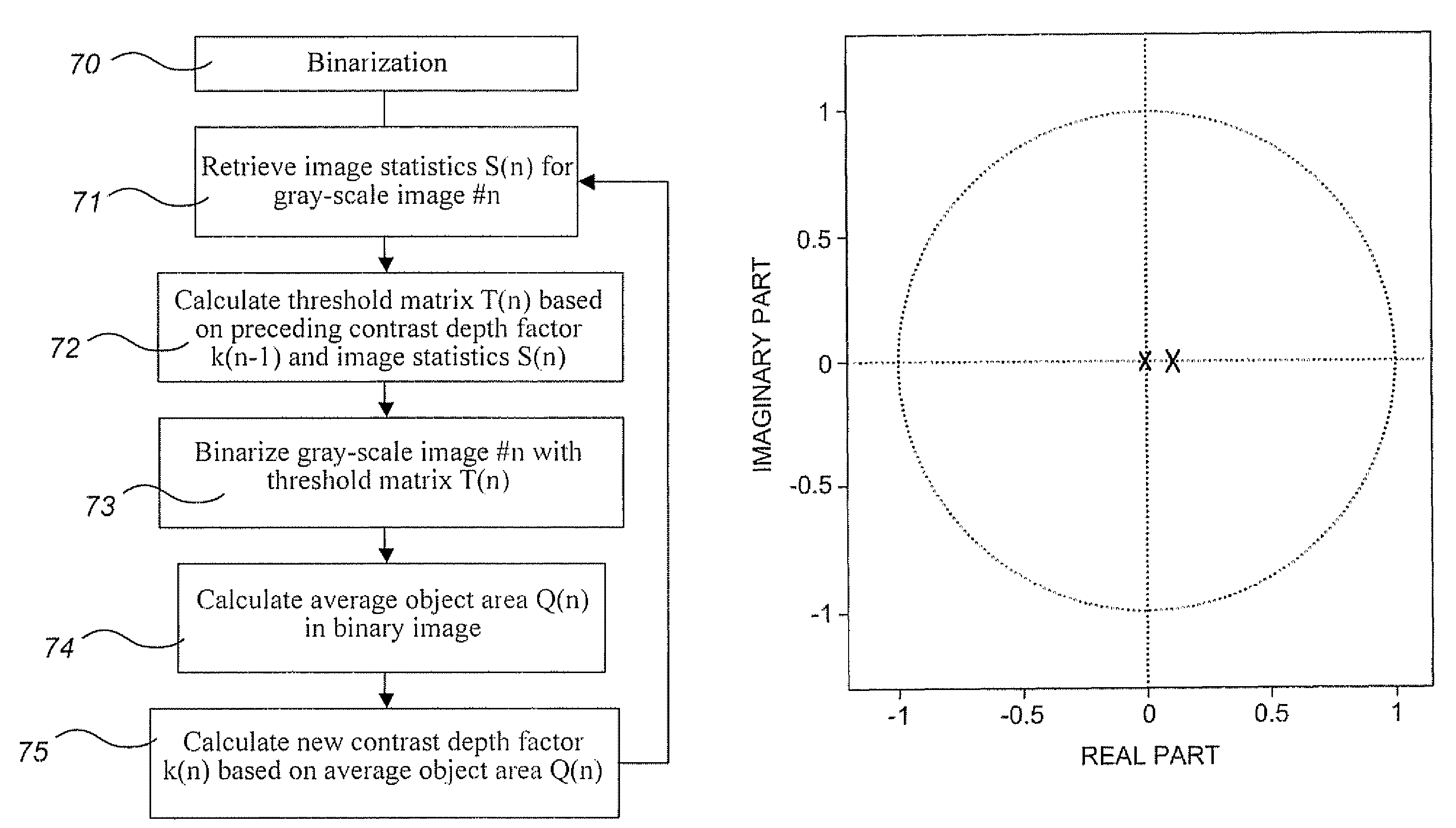
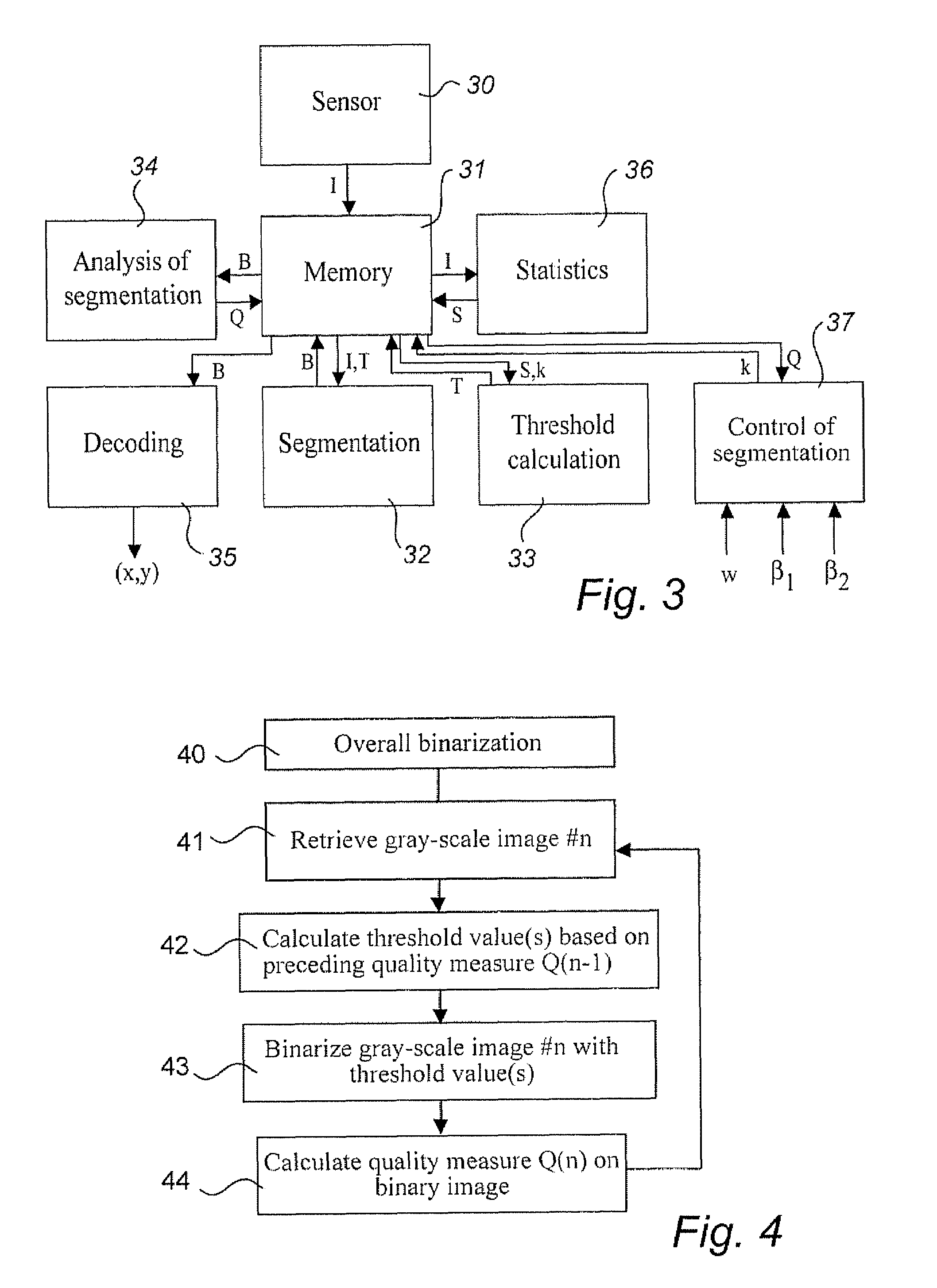
"The present invention provides an improved image-processing technique for identifying objects in a digital image. The technique involves comparing luminance values of a current image with at least one threshold value to create a current binarized image. The quality of the binarized image is then measured and used to update the threshold value for use in binarizing a subsequent image. The technique is tolerant to interference, such as variations in sharpness, background luminance, and signal-to-noise ratio. It is efficient in terms of time and memory requirements. The invention also provides a method for identifying objects in a sequence of images using a feedback control system."

Problems solved by technology

In most cases, unfortunately, high precision can only be achieved at the cost of relatively time-consuming and memory-intensive calculations.
Recording of handwritten information should be carried out at high temporal resolution, typically approximately 50-100 images per second, for which reason it is difficult to combine requirements for high precision in the binarization with requirements for rapid processing and small memory requirement, even in a specially-adapted data processing unit.
In most cases, the images additionally contain interferences, for example in the form of noise, lack of sharpness, uneven illumination and geometric distortion, making the identification of symbols or objects still more difficult.

Method used


Image

  • Method and device for identifying objects in digital images
  • Method and device for identifying objects in digital images
  • Method and device for identifying objects in digital images

Examples


Embodiment Construction

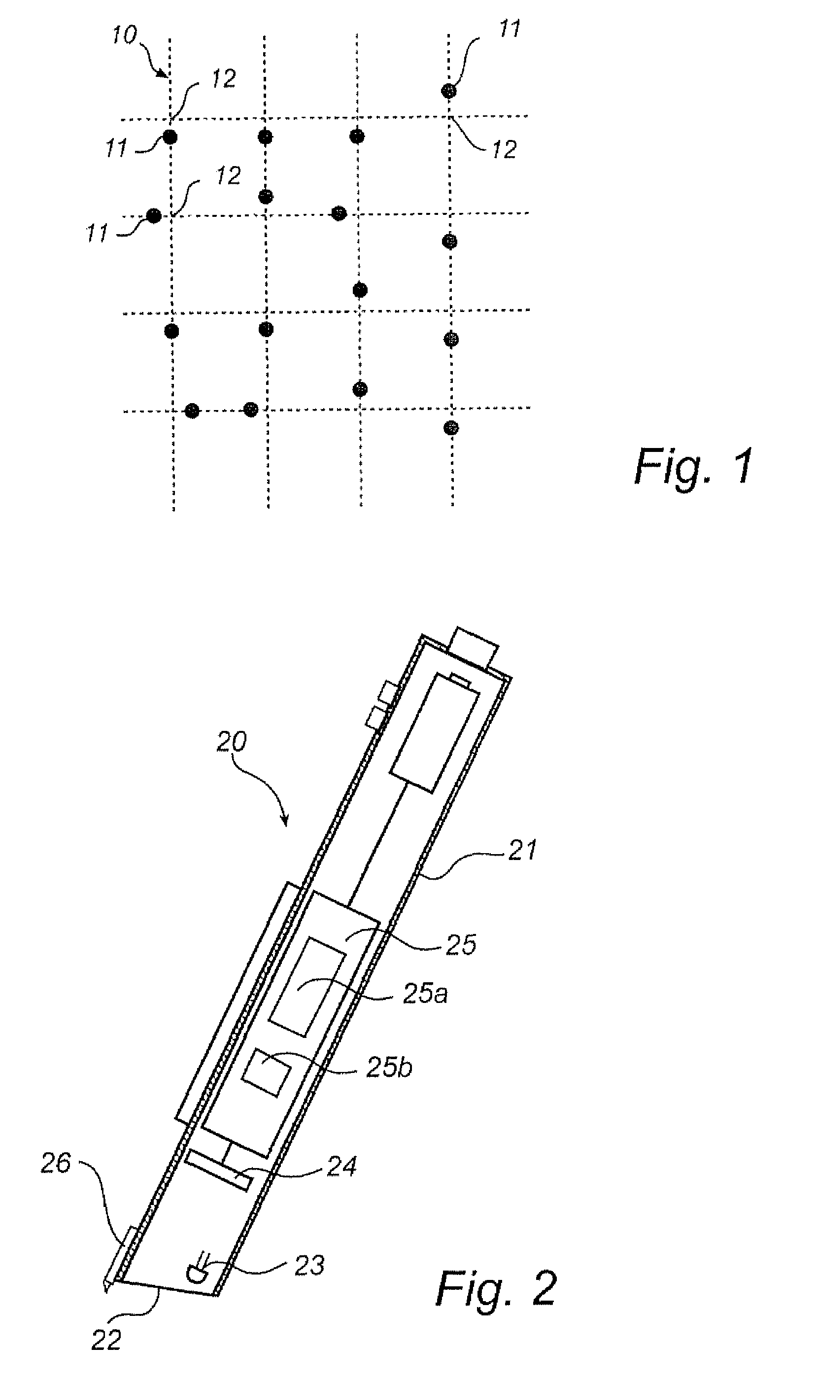
[0045]The description below concerns position determination based on gray-scale images of a position-coding pattern. The position-coding pattern can be of any type, for example any one of the patterns mentioned by way of introduction In the following, however, the invention is illustrated in connection with the pattern which is described in the Applicant's International Patent Publications WO 01 / 16691 and WO 01 / 26033. This pattern is described briefly below with reference to FIG. 1.

[0046]The position-coding pattern comprises a virtual raster 10, which thus is neither visible to the human eye nor can be detected directly by a device which is to determine positions on the surface, and a plurality of marks 11, each of which, depending upon its position, represents one of four values “1” to “4”. The value of the mark 11 depends upon where it is placed in relation to its nominal position 12. The nominal position 12, which can also be called a raster point, is represented by the point of ...


PUM


Abstract

In a method for identifying objects in a digital image which is included in a sequence of images, luminance values of a current digital image are compared with at least one threshold value in order to create a current binarized image on the basis of the comparison. A quality measure for the current binarized image is also calculated, whereupon said at least one threshold value is updated on the basis of the quality measure for use in binarization of a subsequent image. The method can be realized in the form of a computer program, a computer program product, a device, and a hand-held apparatus for position determination.

Description

[0001]This application claims priority on provisional Application No. 60 / 333,164 filed on Nov. 27, 2001, the entire contents of which are hereby incorporated by reference.FIELD OF THE INVENTION[0002]The present invention relates in general to processing of digital images, and more particularly to thresholding or binarization of the same. The invention is particularly, but not exclusively, aimed at preparatory image processing prior to calculation of position information on the basis of the shape and / or location of objects in a digital image.BACKGROUND TO THE INVENTION[0003]In digital image processing, it is sometimes desirable, in what is known as a segmentation process, to separate some form of structure from a background in a digital gray-scale image. This can be done by what is known as thresholding or binarization, in which the luminance values of the pixels of the digital image are compared to a threshold value. For example, luminance values above the threshold value may be set...

Claims


Application Information

Patent Timeline
Patent Type & Authority Patents(United States)
IPC IPC(8): G06K9/36G06K9/38G06T5/00G06V10/28
CPCG06K9/38G06T7/0042G06T2207/20148G06T2207/10048G06T2207/10016G06T7/73G06T7/136G06V10/28
Inventor OLSSON, ANDREAS
Owner ANOTO AB
Learn More