Apparatus for dilution of discharged fuel

a technology for dilution apparatus and discharged fuel, which is applied in the direction of electrical apparatus, fuel cells, cell components, etc., can solve the problem of purged hydrogen gas

Active Publication Date: 2007-10-23
HONDA MOTOR CO LTD
View PDF7 Cites 1 Cited by
  • Summary
  • Abstract
  • Description
  • Claims
  • Application Information

AI Technical Summary

Benefits of technology

[0017]The apparatus described above can collectively treat the purged hydrogen gas as well as water generated in a fuel cell stack and a humidifier. In this way, the apparatus provides an efficient dilution system, allowing a compact and light-weight box of fuel cell system.

Problems solved by technology

This has posed a problem of safe hazard that the purged hydrogen gas is discharged directly into the open air.
In this connection, Japanese Published Patent Application 6-275300 does not disclose an idea that purged hydrogen gas should be discharged into the open air after undergoing a dilution process.

Method used


Image

  • Apparatus for dilution of discharged fuel
  • Apparatus for dilution of discharged fuel
  • Apparatus for dilution of discharged fuel

Examples


first embodiment

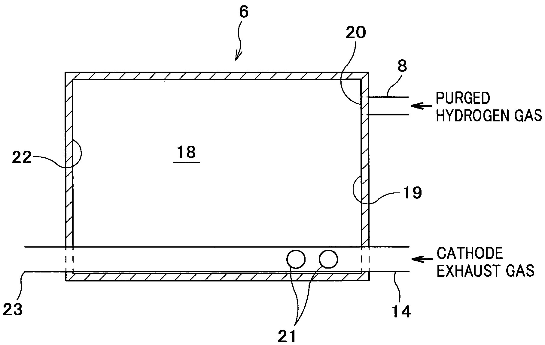
[0034]an apparatus for dilution of discharged fuel according to the present invention is described referring to FIG. 3.

[0035]An apparatus 6 for dilution of discharged fuel is a box-like container and has an inlet 20 at a higher portion of a wall 19, through which purged hydrogen gas coming via a pipe 8 for purged hydrogen gas (FIG. 2) enters the apparatus 6. The inside of apparatus 6 is used as a reservoir 18 for the hydrogen gas coming through the inlet 20.

[0036]A cathode exhaust gas pipe 14, through which cathode exhaust gas coming from a cathode line flows, penetrates horizontally from the wall 19 to a wall 22 at a lower portion of the apparatus 6 and has an outlet 23 communicating with the open air. The cathode exhaust gas pipe 14 has holes 21, which are located near the wall 19 having the inlet 20. The number of holes 21, which in the present embodiment is selected to be two taking into account the efficiency of suction, may be changed to another number as required.

[0037]Using ...

second embodiment

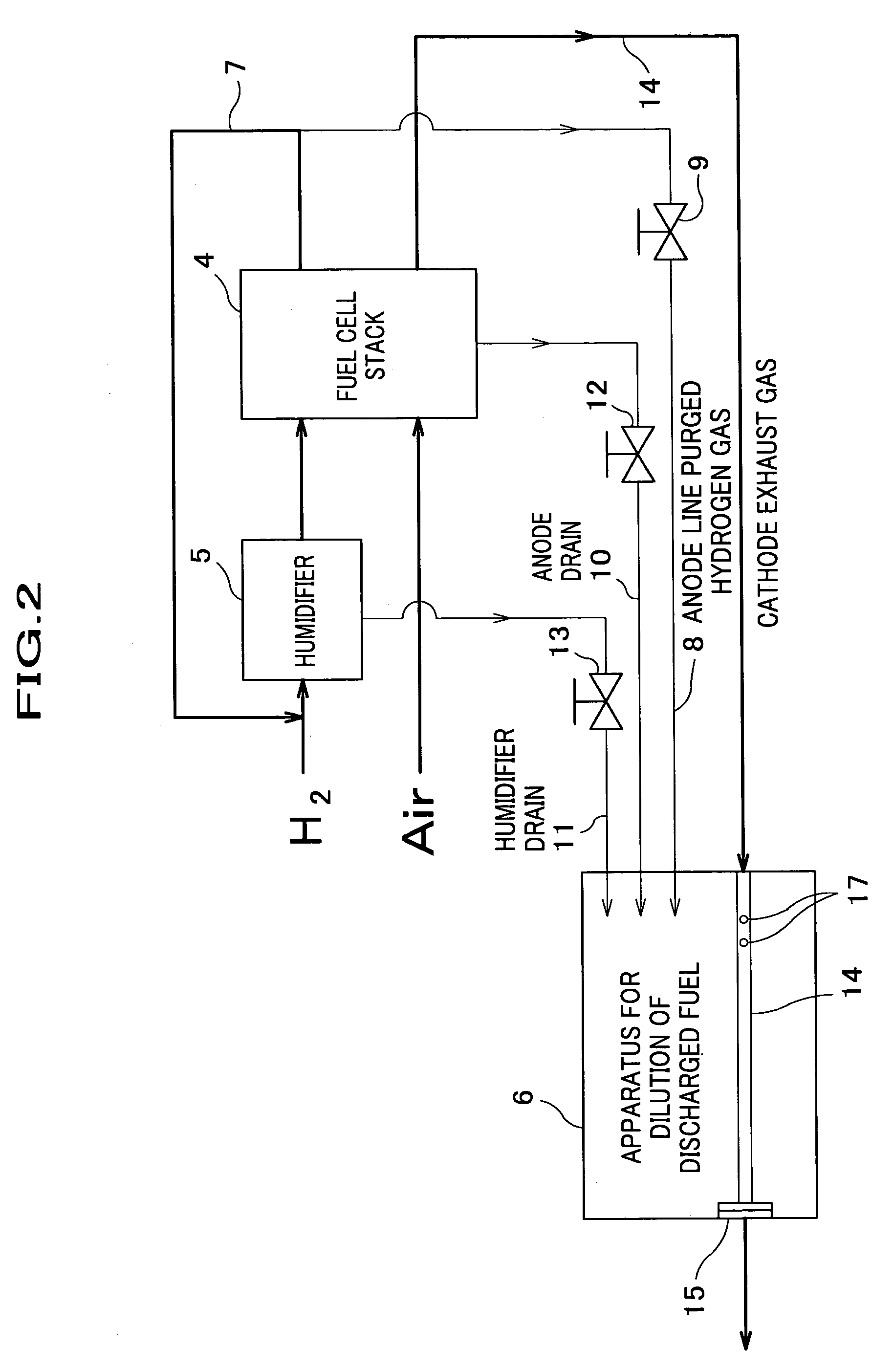
[0042]The apparatus 6 of the second embodiment, in which the inlet 20 and holes 21 are adapted to be spatially apart each other, helps purged hydrogen gas coming into the reservoir 18 to diffuse before it is sucked through the holes 21. In this way, the purged hydrogen gas experiences dilution by expansion and collects in the reservoir 18, resulting in an increase of pressure. A cathode exhaust gas pipe 14, in which the pressure of cathode exhaust gas is lower due to high speed thereof (Bernoulli's theorem), sucks the purged hydrogen gas through the holes 21 and discharges it into the open air mixing with the cathode exhaust gas. The purged hydrogen gas substantially diluted this way, which has low concentration of hydrogen gas, is thus discharged through an outlet 23 into the open air.

[0043]FIG. 5 is a cross sectional view showing an apparatus for dilution of discharged fuel, an example of modification for the second embodiment. In this example, an inlet 20 of pipe 8 for purged hyd...

third embodiment

[0045]An apparatus for dilution of discharged fuel is described referring to FIGS. 6 and 7.

[0046]Description for items which are the same as those of the first embodiment would be omitted, bearing the same symbols.

[0047]An apparatus 6 for dilution of discharged fuel has a horizontal portion 24 with drain holes 25, which has a smaller cross section and is located at the bottom of bent portion of a cathode exhaust gas pipe 14. In this connection, the number of drain holes 25, which is selected to be two in the present embodiment taking into account the efficiency of drain, may be changed to another number as required.

[0048]Condensed water 26 accumulated at the bottom of a reservoir 18, which is contained in purged hydrogen gas discharged into the apparatus 6 through a pipe 8 for purged hydrogen gas, is sucked through the drain holes 25 into the cathode exhaust gas pipe 14, in which cathode exhaust gas running faster causes a pressure drop. In this connection, the condensed water 26 i...


PUM

PropertyMeasurementUnit
diameteraaaaaaaaaa
rectangular shapeaaaaaaaaaa
concentrationaaaaaaaaaa

Abstract

An apparatus for dilution of discharged fuel of a fuel cell is provided, which has an inlet for guiding purged hydrogen gas coming from the fuel cell, a reservoir for storing the purged hydrogen gas guided through the inlet, and a cathode exhaust gas pipe penetrating the reservoir. The cathode exhaust gas pipe has a feature that it has holes inside the reservoir and is supplied with cathode exhaust gas of the fuel cell. Also the apparatus has a feature that the cathode exhaust gas pipe sucks the purged hydrogen gas stored in the reservoir through the holes and discharges the purged hydrogen gas diluted by mixing with the cathode exhaust gas.

Description

FIELD OF THE INVENTION[0001]The present invention relates to an apparatus for dilution of discharged fuel and more specifically to one used for purging operation of a fuel cell system with hydrogen gas, which is mounted on an electric vehicle as a power source.BACKGROUND OF THE INVENTION[0002]In a fuel cell system serving as a power source for an electric vehicle, which employs pure hydrogen gas (hereinafter referred to as hydrogen gas) for example, a circulation system for supplying the hydrogen gas has been selected so as to improve the fuel efficiency. Japanese Published Patent Application 6-275300 reports one example of this system. As a circulation method, an ejector which sucks hydrogen gas by negative pressure or a vacuum pump has been adopted.[0003]Continuation of recirculation for hours in a circulation system sometimes causes a rise in the concentration of impurities in hydrogen gas such as nitrogen, thereby downgrading the efficiency of power generation. Also accumulation...

Claims


Application Information

Patent Timeline
Patent Type & Authority Patents(United States)
IPC IPC(8): H01M8/04H01M2/12H01M8/00H01M8/06
CPCH01M8/04156H01M8/0662H01M8/04126Y02E60/50H01M8/04231
Inventor YAMAMOTO, AKIOFUKUMA, KAZUNORIKOYAMA, TAKATSUGUNUMATA, HIDEOMATSUTANI, MASAHIRO
Owner HONDA MOTOR CO LTD
Why Eureka
Try Eureka