Ultrasonic medical device and method

a transducer and ultrasonic technology, applied in the field of ultrasonic transducer assemblies, can solve the problems of inability to provide uniform pressure, inability to address the present macroscopic stress gradient, and insufficient compression means

Inactive Publication Date: 2007-10-23
CRESCENDO TECH
View PDF17 Cites 273 Cited by
  • Summary
  • Abstract
  • Description
  • Claims
  • Application Information

AI Technical Summary

Problems solved by technology

In previous designs, the compression means may be inadequate and may be unable to provide a uniform pressure across the inside diameter to the outside diameter of each PZT and through the entire PZT stack, the “r” and “z” axes as shown in FIG. 1 and graphically illustrated in FIG. 2.
However, such washers are used primarily to address local stresses and do not address the macroscopic stress gradients present in loaded ultrasonic instruments.
Non-uniform pressure across the r and z axes may reduce transducer efficiency and may lead to high heat generation.
This limitation becomes acutely critical in temperature-limited applications.
In temperature-limited applications, the reduced efficiency translates into higher heat generation in the transducer and reduced maximum output.
Further, non-uniform pressure limits the magnitude of compression and therefore limits the power capability of the transducer.

Method used


Image

  • Ultrasonic medical device and method
  • Ultrasonic medical device and method
  • Ultrasonic medical device and method

Examples


Embodiment Construction

[0041]Before explaining the present invention in detail, it should be noted that the invention is not limited in its application or use to the details of construction and arrangement of parts illustrated in the accompanying drawings and description. Rather, the illustrative embodiments of the invention may be implemented or incorporated in other embodiments, variations, and modifications, and may be practiced or carried out in various ways. Furthermore, unless otherwise indicated, the terms and expressions employed herein have been chosen for the purpose of describing the illustrative embodiments of the present invention for the convenience of the reader and are not for the purpose of limiting the invention.

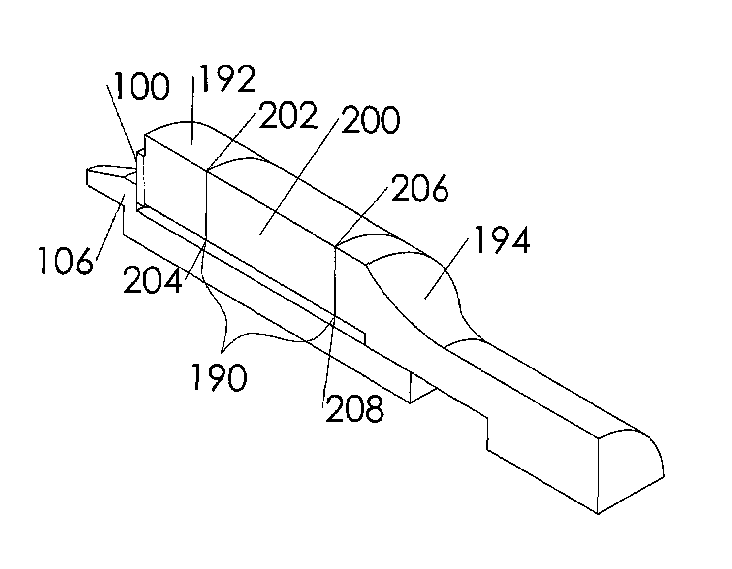
[0042]FIG. 4 illustrates one embodiment of a deformable pressure element 100 in accordance with the present invention. Deformable pressure element 100 may be, for example, a deformable concave disk having a first contact surface 102, a second contact surface 104, an outer perimet...


PUM


Abstract

Ultrasonic devices having transducer assembly including a stack of alternating electrodes and piezoelectric elements. A mounting device having a first and second end is adapted to receive ultrasonic vibration from the stack and transmit it from the first to the second end. A bolt including a head and shaft is configured to threadedly engaged the mounting device. The transducer assembly includes a deformable pressure element having a central opening that permits insertion of the shaft therethrough, and has a convex side facing the bolt head and a concave side facing the stack in a non-deformed state, but, in a deformed state, applies compression forces to the stack based on the deformation. The deformable pressure element may alternately include a surface area, in its deformed state, substantially equivalent to the surface area of a piezoelectric element and / or a first and second beveled surface defining the concave side.

Description

[0001]This application claims the benefit of Provisional Patent Application Ser. No. 60 / 661,739, filed on Mar. 15, 2005, to which priority is claimed pursuant to 35 U.S.C. §119(e) and which is hereby incorporated herein by reference.BACKGROUND OF THE INVENTION[0002](a) Field of the Invention[0003]The present invention relates generally to ultrasonic transducer assemblies and, more particularly, to transducer assemblies of the composite or sandwich type incorporating a deformable pressure element.[0004](b) Description of the Prior Art[0005]Ultrasonic transmission devices are well known for use in a variety of applications such as, for example, surgical operations and procedures. Ultrasonic transmission devices usually include a transducer that converts electrical energy into vibrational motion at ultrasonic frequencies. The vibrational motion is transmitted to vibrate a distal end of a surgical instrument. Such uses are disclosed in representative U.S. Pat. Nos. 3,636,943 and 5,746,7...

Claims


Application Information

Patent Timeline
Patent Type & Authority Patents(United States)
IPC IPC(8): H01L41/08H02N2/00
CPCB06B1/0618B06B1/0611A61B8/4483A61B8/00
Inventor BEAUPRE, JEAN
Owner CRESCENDO TECH
Why Eureka
Try Eureka