Ferro-magnetic force field generator
a magnetic force field and generator technology, applied in the direction of superconducting magnets/coils, magnetic materials, magnetic bodies, etc., can solve the problems of increasing manufacturing costs, spatially uniform magnetic force fields cannot be obtained in such cases, and achieve large magnetic force fields, increase manufacturing costs, and complex device structure
- Summary
- Abstract
- Description
- Claims
- Application Information
AI Technical Summary
Benefits of technology
Problems solved by technology
Method used
Image
Examples
first embodiment
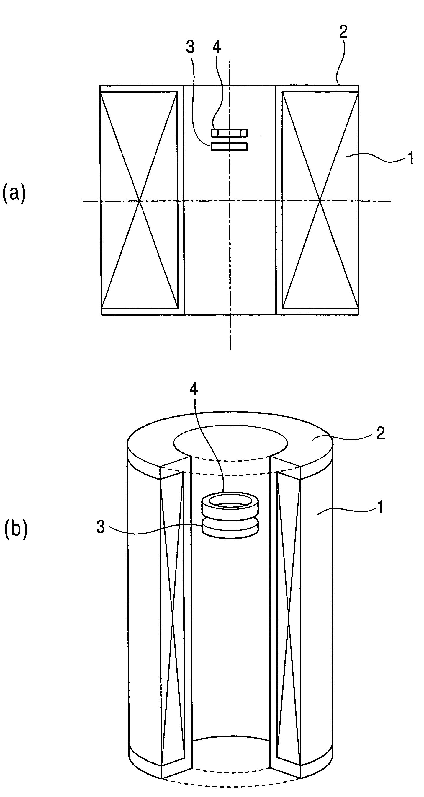
[0047]FIG. 7 is a configuration view of a strong-magnetic-force field generating device to illustrate the present invention.
[0048]In this figure, reference numeral 11 indicates a superconducting magnet, 12 is a winding frame for the superconducting magnet, 13 is a disc ferromagnetic element arranged in a bore of the superconducting magnet 11, and 14 is a ring ferromagnetic element arranged in the bore of the superconducting magnet 11. In this case, the disc ferromagnetic element 13 is positioned at a height of 70 mm from the center of the superconducting magnet, and the ring ferromagnetic element 14 is positioned at a height of 92 mm from the center of the superconducting magnet.
[0049]The commercially-available superconducting magnet 11 having the specification shown in Table 1 is used, and the disc ferromagnetic element 13 and the ring ferromagnetic element 14, which are made of pure iron, are arranged above the equatorial plane of the bore of the superconducting magnet 11, as show...
second embodiment
[0063]FIG. 12 is a configuration view of a strong-magnetic-force field generating device to illustrate the present invention.
[0064]In this figure, reference numeral 31 indicates a first superconducting magnet 31, 32 is a winding frame for the first superconducting magnet 31, 33 is a disc ferromagnetic element, 34 is a ring ferromagnetic element, 35 is a second superconducting magnet coaxially arranged outside the first superconducting magnet 31, and 36 is a winding frame for the second superconducting magnet.
[0065]Since two superconducting magnets are used in such a manner, the present invention is also effective for a case of a superconducting magnet capable of generating a large magnetic field.
third embodiment
[0066]FIG. 13 is a configuration view of a strong-magnetic-force field generating device to illustrate the present invention.
[0067]In this figure, reference numeral 41 indicates a superconducting magnet, 42 is a winding frame for the superconducting magnet 41, 43 and 43′ are disc ferromagnetic elements, 44 and 44′ are ring ferromagnetic elements, 45 is a cryostat for the superconducting magnet 41, and 46 is a support. The support 46 is made of non-magnetic material and is used for fixing the disc ferromagnetic element 43 and the ring ferromagnetic element 44 to the cryostat 45.
[0068]In this embodiment, the disc ferromagnetic element 43 and the ring ferromagnetic element 44, which are of the same material and shape as the first embodiment, are further arranged at an axi-symmetric position in the bore of the superconducting magnet 41. That is, two sets of the disc ferromagnetic elements 43 and 43′ and the ring ferromagnetic elements 44 and 44′ are set.
[0069]According to this approach,...
PUM
| Property | Measurement | Unit |
|---|---|---|
| absolute temperature | aaaaa | aaaaa |
| magnetic field | aaaaa | aaaaa |
| magnetic field | aaaaa | aaaaa |
Abstract
Description
Claims
Application Information
 - R&D
- Intellectual Property
- Life Sciences
- Materials
- Tech Scout
- Unparalleled Data Quality
- Higher Quality Content
- 60% Fewer Hallucinations
Browse by: Latest US Patents, China's latest patents, Technical Efficacy Thesaurus, Application Domain, Technology Topic, Popular Technical Reports.
© 2025 PatSnap. All rights reserved.Legal|Privacy policy|Modern Slavery Act Transparency Statement|Sitemap|About US| Contact US: help@patsnap.com


