
Interactive viewpoint video employing viewpoints forming an array

a viewpoint and array technology, applied in the field of video generation and rendering, can solve the problems of not being able to achieve the goal of allowing users to interactively change to any desired viewpoint, providing significant further complication, and not being able to achieve the goal of achieving the goal. , to achieve the effect of reducing the cost and facilitating the transfer of the capture system

Inactive Publication Date: 2007-10-23
MICROSOFT TECH LICENSING LLC
View PDF7 Cites 52 Cited by
  • Summary
  • Abstract
  • Description
  • Claims
  • Application Information

AI Technical Summary

Benefits of technology

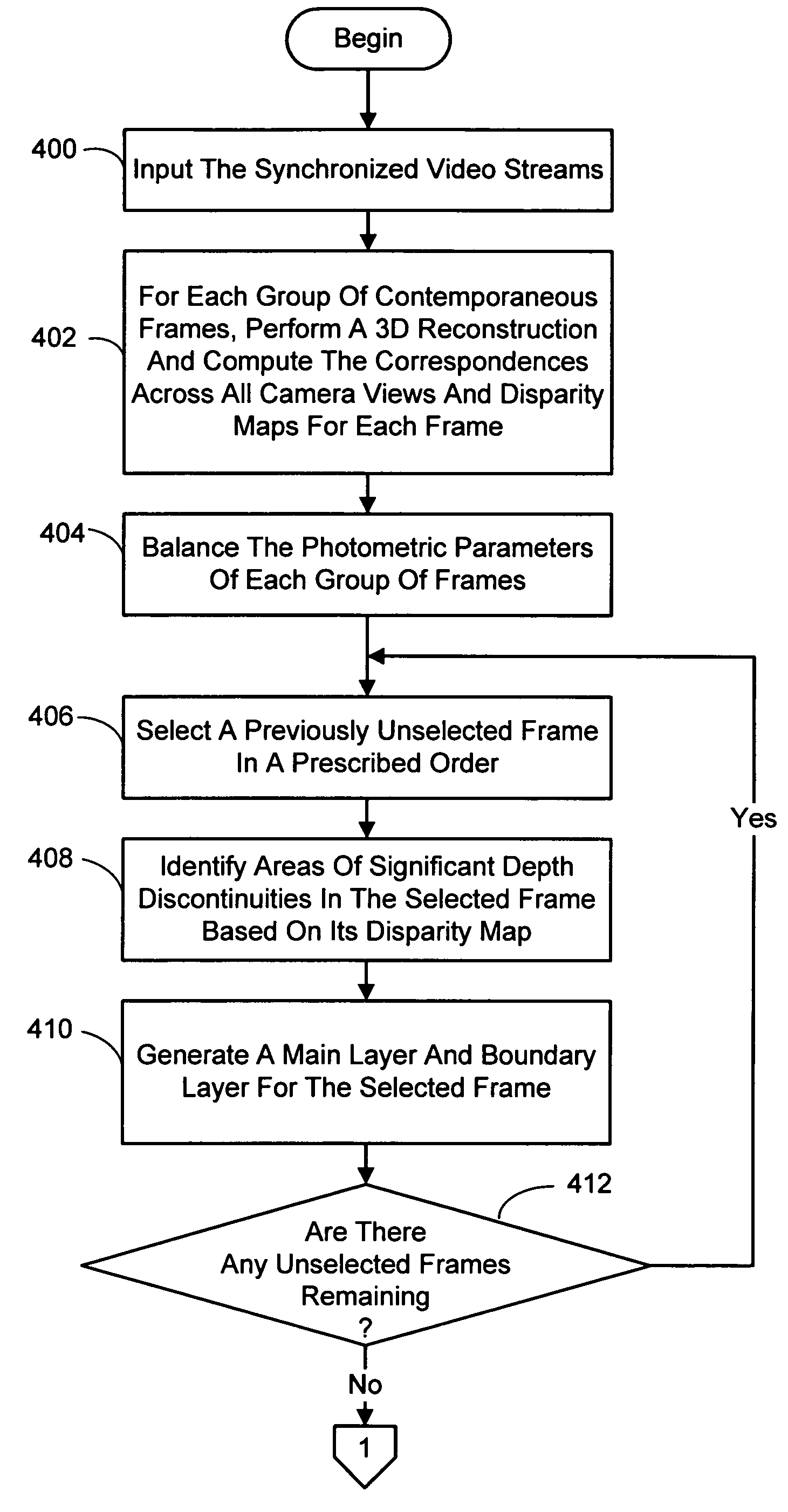
[0020]The present invention is directed toward a system and process for first generating, and then rendering and displaying an interactive viewpoint video in which a user can watch a dynamic scene while manipulating (freezing, slowing down, or reversing) time and changing the viewpoint at will. Since different trajectories can be taken through space-time, no two viewing experiences need be the same. In general, this is accomplished with a system and process that uses a small number of cameras to capture multiple high-quality video streams of a scene. Not only does this reduce the cost associated with capturing the video streams needed to render the scene from a variety of viewpoints over existing methods, but is also advantageous as it makes the capture system portable. A multi-view 3D reconstruction and matting technique is next employed to create a layered representation from the video frames that enables both efficient compression and interactive playback of the captured dynamic scene, while at the same time allowing real-time rendering.
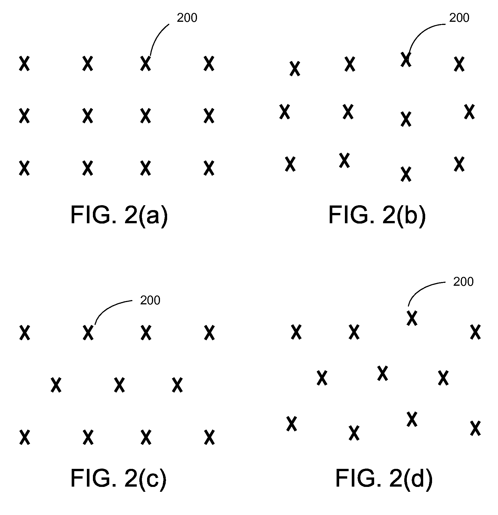
[0023]The video cameras can be high resolution cameras as this will improve the quality of the interactive viewpoint video that is generated. In addition, the cameras can have a genlock feature to facilitate synchronizing the video streams. Further, it would be advantageous for ease in processing the video streams if the cameras are capable of adding metadata to each video frame generated. This metadata would include, for example, the current settings and exposure level of the camera, and a timestamp.

Problems solved by technology

Unfortunately, this effect is a one-time, pre-planned affair.
Thus, existing systems would not allow a user to interactively change to any desired viewpoint while watching a dynamic image-based scene.
However, extending IBR to dynamic scenes is not trivial because of the difficulty (and cost) of synchronizing so many cameras as well as acquiring and storing the images.
Not only are there significant hurdles to overcome in capturing, representing, and rendering dynamic scenes from multiple points of view, but being able to do this interactively provides a significant further complication.
To date attempts to realize this goal have not been very satisfactory.
Unfortunately, the results look unrealistic because of low resolution, matching errors, and improper handling of object boundaries.
However, it is an expensive system, and provides single viewpoint depth only, which makes it less suitable for multiple view-point video.
However, despite all the advances in stereo and image-based rendering, it is still very difficult to interactively render high-quality, high resolution views of dynamic scenes.

Method used


Image

  • Interactive viewpoint video employing viewpoints forming an array
  • Interactive viewpoint video employing viewpoints forming an array
  • Interactive viewpoint video employing viewpoints forming an array

Examples


Embodiment Construction

[0041]In the following description of the preferred embodiments of the present invention, reference is made to the accompanying drawings which form a part hereof, and in which is shown by way of illustration specific embodiments in which the invention may be practiced. It is understood that other embodiments may be utilized and structural changes may be made without departing from the scope of the present invention.

1.0 Interactive Viewpoint Video

[0042]The ability to interactively control viewpoint while watching a video is an exciting new application for image-based rendering. The present system and process provides this capability by rendering dynamic scenes with interactive viewpoint control using multiple synchronized video streams combined with novel image-based modeling and rendering techniques. Because any intermediate view can be synthesized at any time, with the potential for space-time manipulation, the present approach has been dubbed interactive viewpoint video.

[0043]A ke...


PUM


Abstract

A system and process for generating, and then rendering and displaying, an interactive viewpoint video in which a user can watch a dynamic scene while manipulating (freezing, slowing down, or reversing) time and changing the viewpoint at will. In general, the interactive viewpoint video is generated using a small number of cameras to capture multiple video streams. A multi-view 3D reconstruction and matting technique is employed to create a layered representation of the video frames that enables both efficient compression and interactive playback of the captured dynamic scene, while at the same time allowing for real-time rendering.

Description

CROSS-REFERENCE TO RELATED APPLICATION[0001]This application is a continuation-in-part of a prior application entitled “Interactive Viewpoint Video System And Process” which was assigned Ser. No. 10 / 880,774 and filed Jun. 28, 2004.BACKGROUND[0002]1. Technical Field[0003]The invention is related to the generation and rendering of video, and more particularly to a system and process for generating and rendering an interactive viewpoint video in which a user can watch a dynamic scene while changing the viewpoint at will.[0004]2. Background Art[0005]For several years now, viewers of TV commercials and feature films have been seeing the “freeze frame” effect used to create the illusion of stopping time and changing the camera viewpoint. The earliest commercials were produced by using a film-based system, which rapidly jumped between different still cameras arrayed along a rail to give the illusion of moving through a frozen slice of time.[0006]When it first appeared, the effect was fresh...

Claims


Application Information

Patent Timeline
Patent Type & Authority Patents(United States)
IPC IPC(8): G09G5/00G06T15/20G06T19/00
CPCG06T7/0077H04N5/2627G06T15/205G06T2207/10021G06T7/596G06T7/557
Inventor KANG, SING BINGZITNICK, III, CHARLESUYTTENDAELE, MATTHEWWINDER, SIMONSZELISKI, RICHARD
Owner MICROSOFT TECH LICENSING LLC
Learn More