Visual aid in the form of telescopic spectacles with an automated focusing device

a technology of automatic focus and visual aid, which is applied in the field of visual aid, can solve the problems of affecting the resistance of the system to mechanical stress, and affecting the wear comfort of users, so as to eliminate the possibility of defective vision

Inactive Publication Date: 2007-10-23
LEICA INSTR SINGAPORE PTE
View PDF20 Cites 34 Cited by
  • Summary
  • Abstract
  • Description
  • Claims
  • Application Information

AI Technical Summary

Benefits of technology

[0014]The object of the invention is to make available a vision aid which is worn on the head and which allows the user to change the working distance and to use different magnification factors which are matched to the respective activity. Furthermore, the 3-D image will be preserved without the position of the two tubes of the vision a

Problems solved by technology

(1) The tubes are mechanically adjusted by motors via gearing; this means a relatively great weight and thus little wearing comfort for the user.
(2) Since the tubes of the vision aid must be made movable to one another according to the lengthwise axis, the resistivity of the system to mechanical stress suffers.
This can lead to disruptive reflections and to a reduction in the size of the entry pupil and thus of the visual field.
(4) In practice it is hardly possib

Method used


Image

  • Visual aid in the form of telescopic spectacles with an automated focusing device
  • Visual aid in the form of telescopic spectacles with an automated focusing device
  • Visual aid in the form of telescopic spectacles with an automated focusing device

Examples


Embodiment Construction

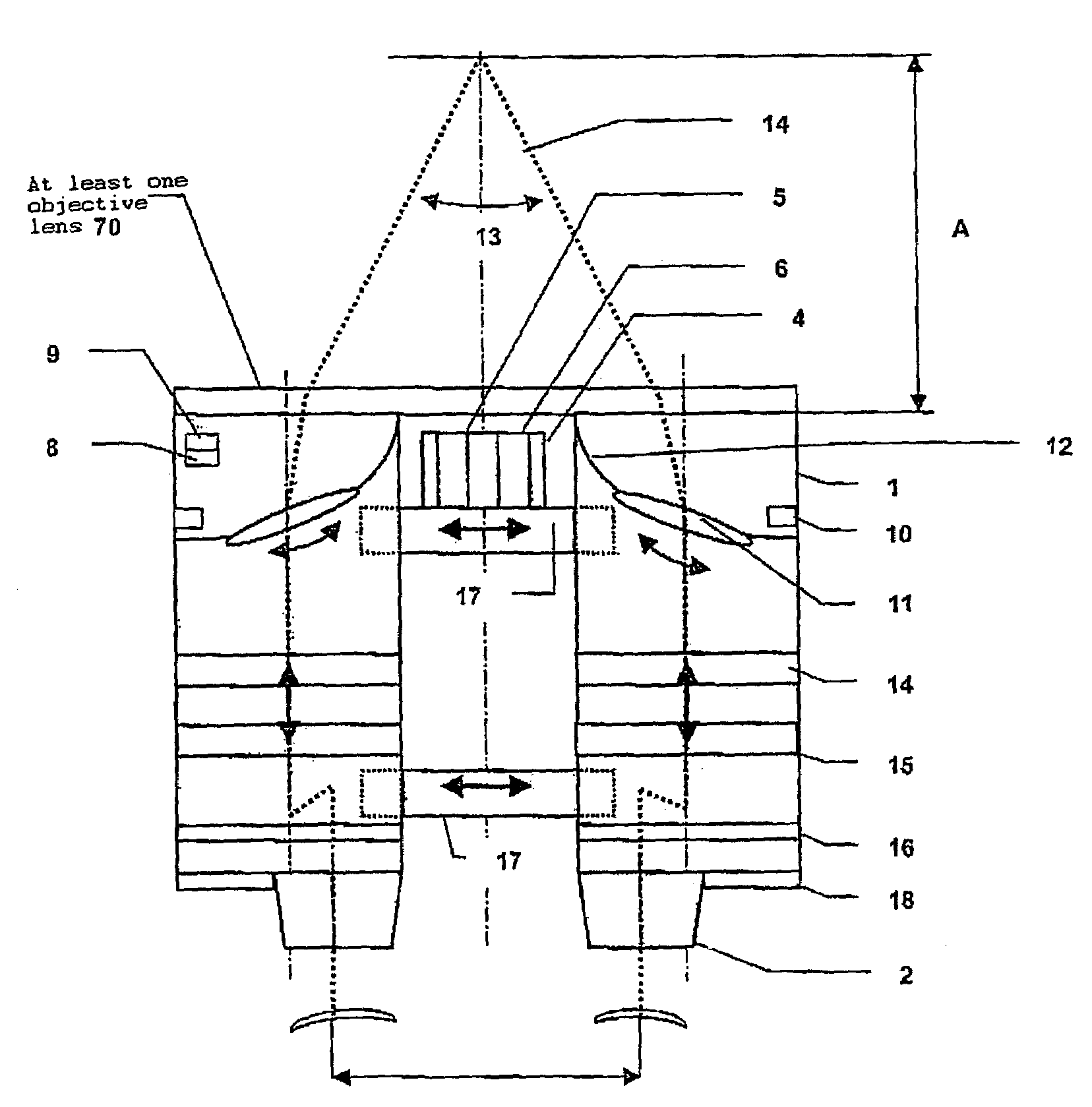
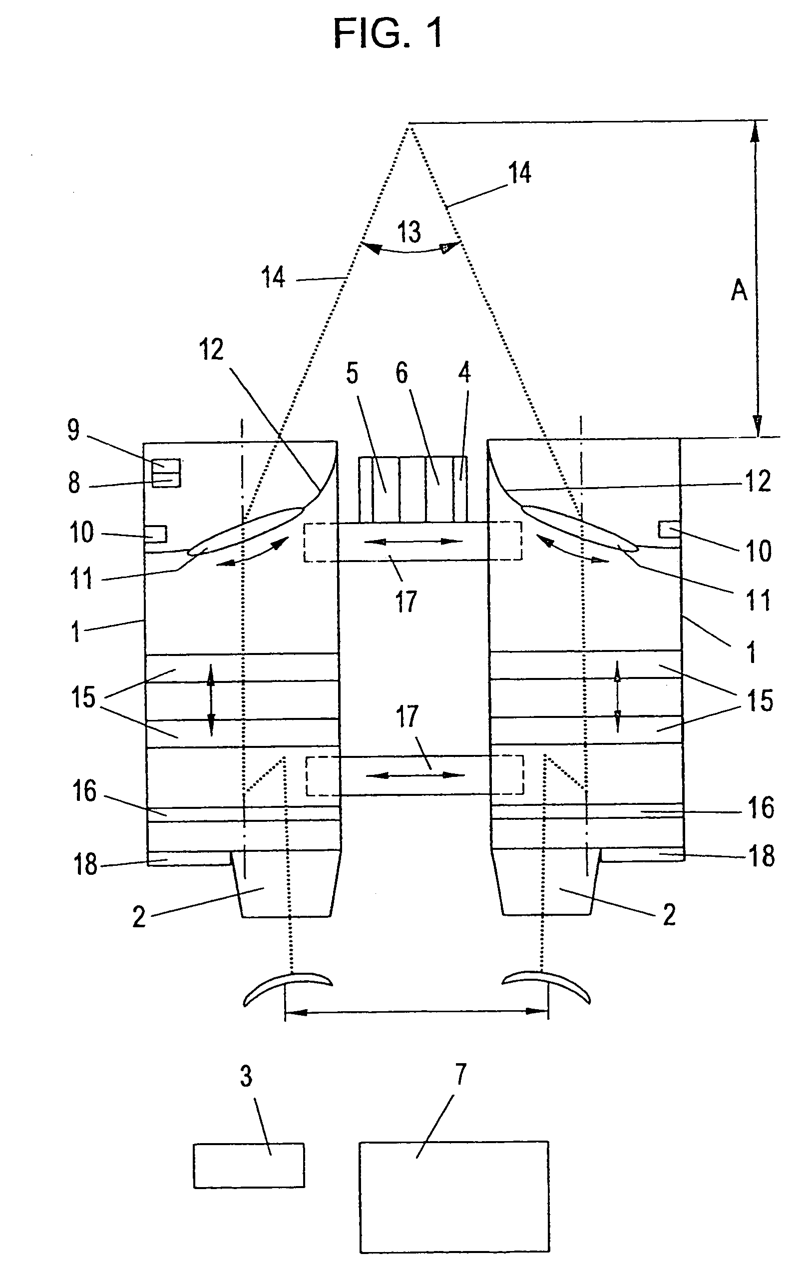
[0056]FIG. 1 shows a vision aid (“telescopic spectacles”) consisting of two tubes 1, eyepiece parts 2, an autofocussing means 4 which is mounted in the middle in this embodiment with an infrared diode 5 and a receiving unit 6. The tubes 1 can be connected to one another fixed, or as shown in FIG. 1, by segments 17 of adjustable length. An external switch 3 and an external electronic unit 7 can be connected to the vision aid by cable, or, as in this embodiment, without a cable, for example by radio transmitters 8 and radio receivers 9 or otherwise.

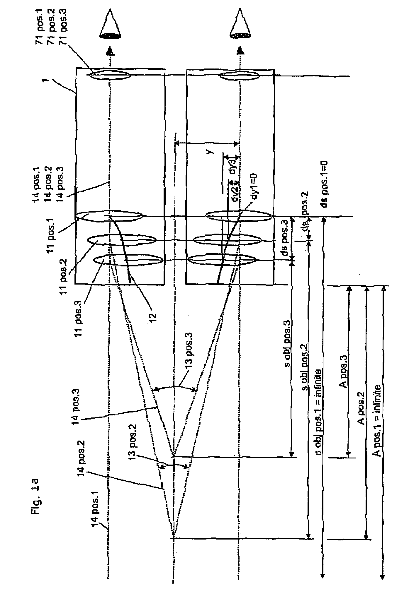
[0057]FIG. 1 furthermore shows two bent boards in this example which are housed in the tubes 1 as guides 12 on which optical elements 11 can be moved back and forth by servomotors 10 such that the refractive property of their respective position yields the angle 13 necessary for each selected working distance A between the beam paths 14 emerging from the tubes 1. As seen in FIG. 1 and FIG. 1a, the guides 12 are curved such that as the worki...


PUM


Abstract

A vision aid in the form of telescopic spectacles has two lens systems, which each comprise at least one objective lens (70) and one eyepiece (71). An autofocussing element which changes the focal length of the lens systems for sharp focussing thereof according to the distance of the telescopic spectacle from the object is assigned to the lens systems. Furthermore, an element for changing the magnification factor by changing the focal length of the lens systems (“zoom”) and finally an element for matching the parallax between the lens systems of the vision aid to the focal length which has been set according to the distance of the telescopic spectacles from the object are assigned to the lens systems. The parallax is adapted using adjustable optical elements (11) which are located in the beam path of the lens systems, with which elements the angle (13) between the beam paths (14) running from the lens systems (1) to the object can be changed.

Description

BACKGROUND OF THE INVENTION[0001]The invention relates to a vision aid with an autofocussing means, with a means for changing the focal length and with a means for matching the parallax between the tubes of the vision aid to the respectively set focal length.[0002]One such vision aid (telescopic spectacles) with an autofocussing means, with a means for changing the focal length and with a means for matching the parallax between the tubes of the vision aid to the respectively set focal length, is disclosed in WO 96 / 09566 A (or the essentially identical U.S. Pat. No. 5,971,540 A). The known vision aid is intended for use as telescopic spectacles.[0003]The known telescopic spectacles have an automatic and / or manual focussing means, a device for manually changing the magnification factor, and a device for automatic, mechanical parallax compensation corresponding to the respective focal length. If for example during vascular surgery, as a result of the location of the various surgical si...

Claims


Application Information

Patent Timeline
IPC IPC(8): G02B23/00A61B19/00G02B5/30G02B7/28G02B25/00G02B27/00G02B27/01G02B27/02G02C7/08
CPCG02B7/002G02B25/004G02C7/088G02B27/0172G02B27/0176G02B27/017G02B5/30G02B2027/0132G02B25/00
Inventor OFNER, ANTON GERALD
Owner LEICA INSTR SINGAPORE PTE
Why Eureka
Try Eureka