
Heald, particularly for rapidly running weaving machines

a rapid running, weaving machine technology, applied in the field of healds, can solve the problems of large waste during manufacture, reduced raw material quantity, and difficulty in reducing the quantity of raw materials, and achieve the effect of facilitating the yarn run

Inactive Publication Date: 2007-10-30
GROZ BECKERT KG
View PDF33 Cites 4 Cited by
  • Summary
  • Abstract
  • Description
  • Claims
  • Application Information

AI Technical Summary

Benefits of technology

[0012]The above measures not only minimize waste, but also reduce the weight of the heald which makes possible a further increase in the weaving speed.
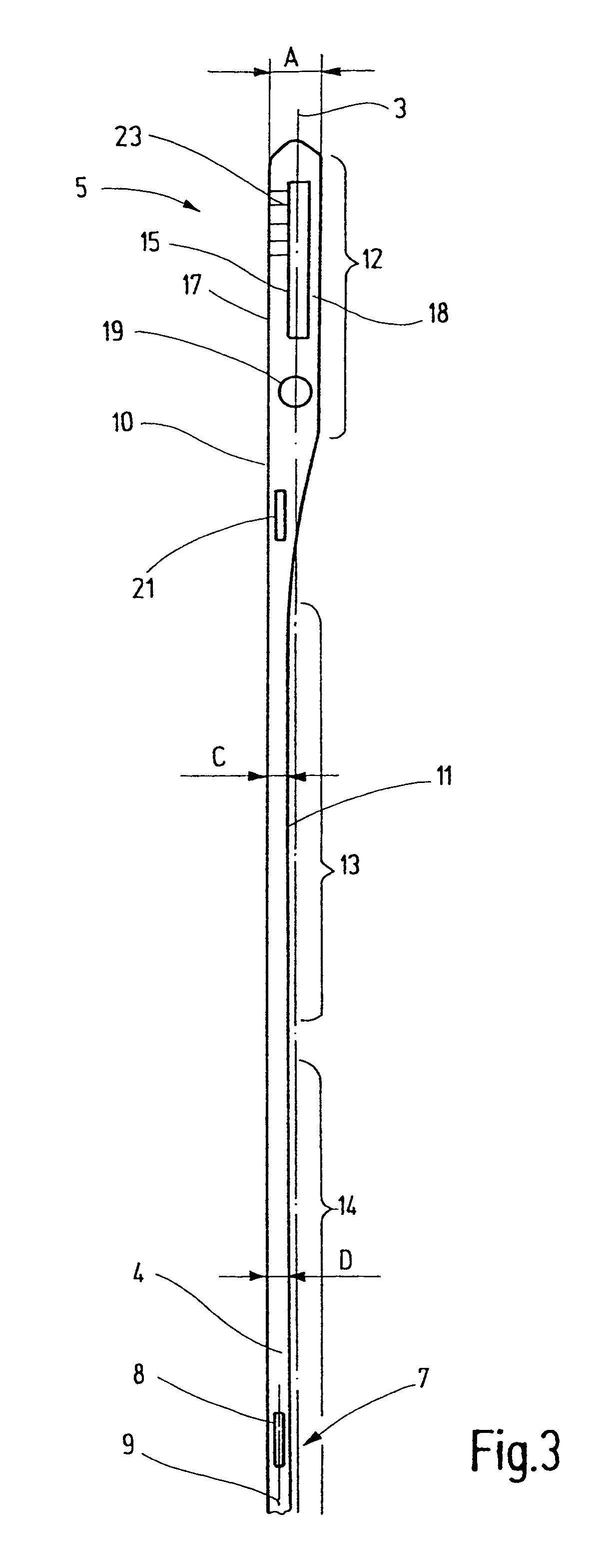
[0014]It has been found expedient to provide that the width of the end eyelet is at least 1.8 times the width of the heald in the region of the yarn eyelet. This ensures more than a sufficient stability of the end eyelet. This applies particularly, if the end eyelet is a closed, approximately rectangular annulus. Such end eyelets are also referred to as O-shaped end eyelets. Such an end eyelet preferably has two mutually essentially parallel, longitudinal webs which are preferably entirely straight. One of the webs borders the straight edge (and constitutes a portion thereof), while the other web is arranged at the oppositely located side of the heald. The web bordering the straight edge is preferably wider than the web spaced from the straight edge. Such an arrangement has at least two advantages: First, the acceleration or braking forces and, in general, all forces introduced in this manner by the shaft stave into the heald are transmitted reliably and with only slight stresses on the heald. Further, a relatively large transverse offset is obtained between the yarn eyelet and a line interconnecting the end eyelets. This increases the distance of the yarn eyelets in heald arrangements having frequently desired dual yarn eyelet sets.
[0016]While the edge situated on one side of the heald lies on a straight line, the oppositely located edge is preferably subdivided into portions which are straight by themselves, but which lie on lines parallel to one another. As a result, on the one hand, the heald weight is minimized and, on the other hand, a stabile heald of tensile resistance is obtained.
[0017]Preferably, between the yarn eyelet and the end eyelets the heald body has a portion whose width is less than the width of the yarn eyelet, whereby the heald weight may be further minimized.
[0019]Preferably, the heald body is twisted at its yarn eyelet. This then means that one part of the heald body surrounding the yarn eyelet is slightly turned out of the plane which the flat material defines at other parts of the heald body. This measure facilitates the yarn run.
[0020]The heald body is preferably made of tempered steel. If required, other flat materials may find application. The flat material may be provided with one or more undulations for maintaining adjoining healds at a distance from one another. The undulations give rise to a certain spring effect which may be advantageous.

Problems solved by technology

Although by such a measure the quantity of raw material may be reduced, a critical connecting location between heald and end eyelet exists which may give rise to problems in rapidly operating weaving machines.
As noted earlier, however, such healds too, have the disadvantage of large waste during manufacture.

Method used


Image

  • Heald, particularly for rapidly running weaving machines
  • Heald, particularly for rapidly running weaving machines
  • Heald, particularly for rapidly running weaving machines

Examples


Embodiment Construction

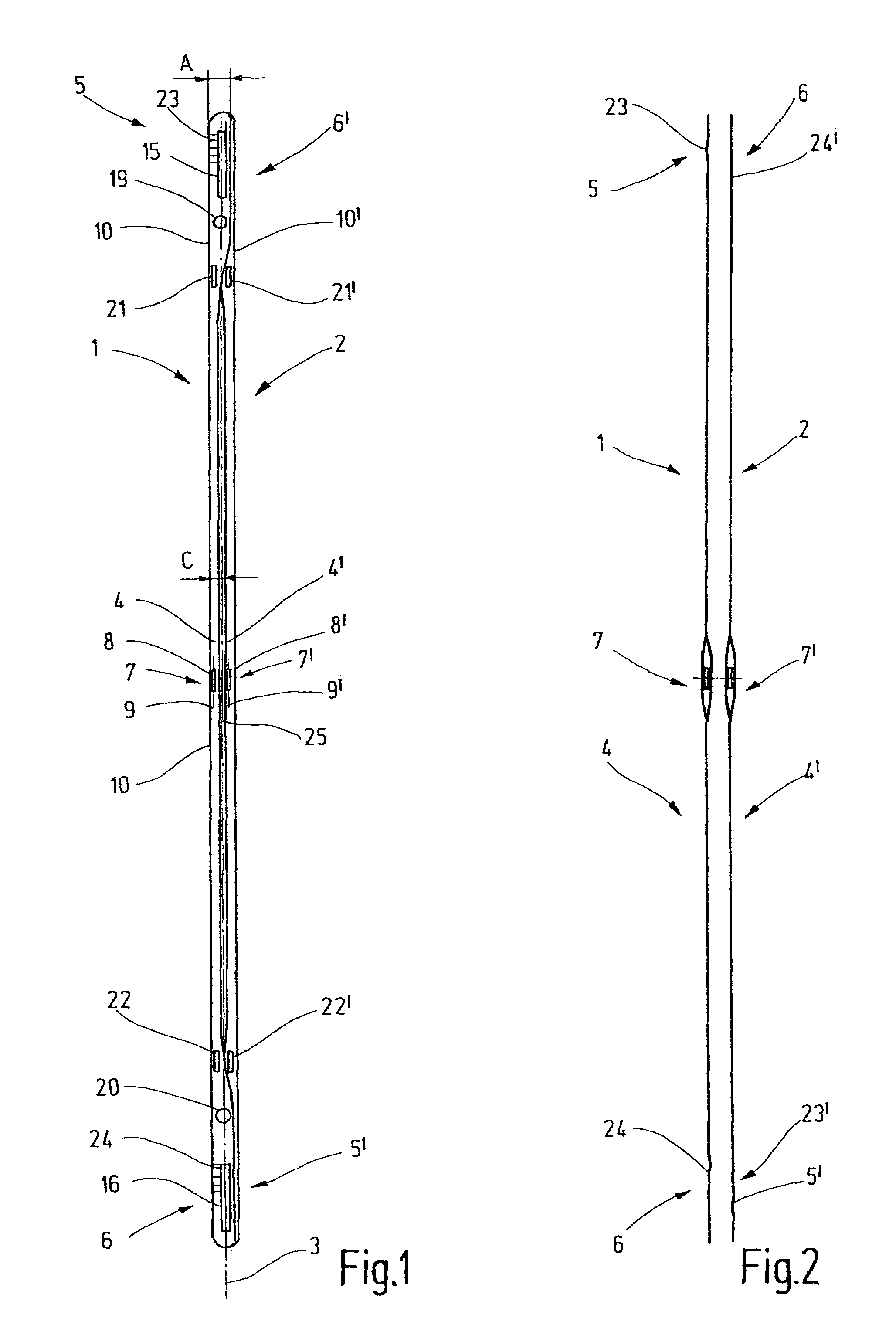
[0027]FIG. 1 shows two healds 1, 2 of identical structure, superposed on one another in a position turned 180°. The healds 1, 2 are to be assembled in a heald shaft and, with the latter, serve for guiding the warp yarns and for shed-forming. In addition to the heald 1, further healds are stacked above one another parallel to the plane of the drawing in the same arrangement and are to a certain extent flush with the heald 1. Likewise, further identical and thus flush healds are associated with the heald 2. Preferably, the healds of the arrangement pertaining to the heald 1 alternate with the healds of the arrangement pertaining to the heald 2. The description of the heald 1 which follows applies equally and correspondingly to the heald 2 which in FIG. 1 is arranged in a mirror image to the heald 1, relative to a line of symmetry 3. The details of the heald 2 are provided in FIG. 1 with the same reference numerals as the details of the heald 1. They are provided with an apostrophe mer...


PUM


Abstract

An improved heald consists of a flat material, such as tempered steel. It has closed (O-shaped) end eyelets (5, 6) which are one-piece parts of the heald body (4). An edge (10) which extends along the full length of the heald (1), is of entirely straight configuration. In contrast, the oppositely-located edge (11) consists of offset straight portions. A particularity of the heald according to the invention resides in the fact that the openings (15, 16) provided in the end eyelets (5, 6) for receiving the shaft staves are eccentrically arranged, whereby the two webs (17, 18) bordering the openings (15, 16) have unlike widths. With a reduced material input and weight a heald is obtained which, as concerns stability and possibility of utilization in existing weaving systems is at least equivalent to conventional healds.

Description

CROSS REFERENCE TO RELATED APPLICATION[0001]This application claims the priority of German Patent Application No. 10 2005 033 175.0, filed on Jul. 13, 2005, the subject matter of which, in its entirety, is incorporated herein by reference.BACKGROUND OF THE INVENTION[0002]The invention relates to a heald having features as defined in the preamble of claim 1.[0003]Healds designed for high-performance weaving machines are usually made of tempered steel for ensuring structural strength. The band width of the steel ribbon for manufacturing such healds has been worldwide standardized as being from 5.5 mm to 6 mm. Since the healds, because of the high operating speeds of the weaving machines, should be as light as possible despite the high specific mass of steel, in the length direction of the heald as large portions of the ribbon as possible are removed by punching and the thus-obtained edges are subsequently polished.[0004]By punching out portions of the ribbon during the manufacturing p...

Claims


Application Information

Patent Timeline
Patent Type & Authority Patents(United States)
IPC IPC(8): D03C9/02D03C9/04D03C7/06
CPCD03C9/02D03C9/024
Inventor MATHEWS, OLIVER HANS
Owner GROZ BECKERT KG
Learn More