
Expandable laser catheter

Inactive Publication Date: 2007-10-30
SPECTRANETICS
View PDF9 Cites 75 Cited by
  • Summary
  • Abstract
  • Description
  • Claims
  • Application Information

AI Technical Summary

Benefits of technology

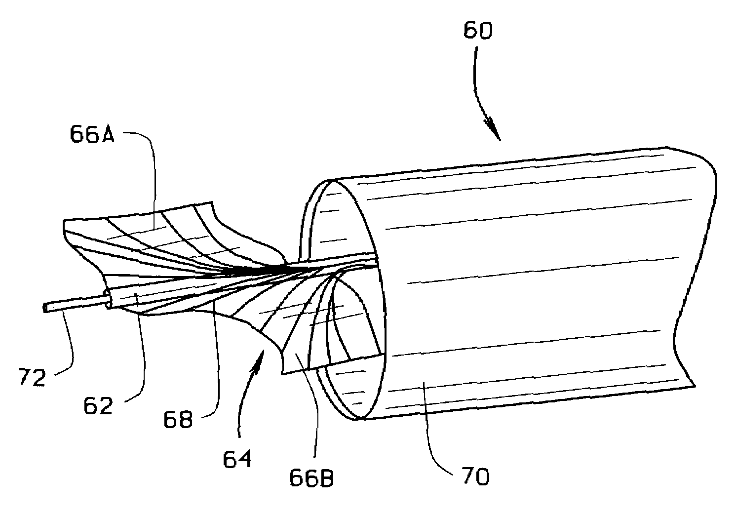
[0011]In an alternative embodiment, the laser catheter utilizes mechanical spring force to expand the distal end of the laser catheter. In this alternative embodiment, the optical fibers are attached to a stiff shaftway. A fin structure including a plurality of fins fabricated from a spring material is attached to the distal end of the shaftway. The stiff shaftway is capable of transmitting torque to the distal end so that the fin structure can be rotated, thus facilitating advancement of the fin structure, and complete removal of the obstruction. The fins have a substantially rolled shape and are expandable from a retracted position to an extended position. In both the retracted position and the extended position the fins retain a substantially rolled shape which substantially conforms to the inner dimensions of the body passage, to minimize damage to the inner wall of the body passage. At the fin structure the ends of the optical fibers are attached and spread across the fins and are directed parallel to the shaftway. The laser catheter further includes an outer catheter body or sheath slidably disposed over the shaftway to retain the fin structure in the retracted position.
[0012]In use of the alternative embodiment, a guide wire is introduced into a body passage and advanced past the obstruction. The laser catheter is introduced over the guide wire and advanced toward the obstruction. When the distal end of the catheter is adjacent the obstruction, the shaftway is rotated and advanced so that the fin structure is pushed out of the outer catheter body, thus releasing the fins from the retracted position and allowing them to expand to the extended position. In the extended position, the fins contact the passage inner wail and the ends of the optical fibers are directed parallel to the inner wall of the passage. The fin structure can be further advanced along the passage wall by advancing the shaftway and sliding the fin structure along the passage wall. Laser energy is used to photoablate regions of the obstruction targeted by the optical fibers. The mounting of the optical fibers on the fin structure allows the obstruction to be removed from around the passage central axis (around the guide wire) to the outside diameter of the passage, with the fins protecting normal passage inner wall from photoablation. When the obstruction has been removed, the fin structure is rotated and pulled back into the outer catheter body, thus causing the fins to retract to the retracted position. The catheter is then removed from the body passage.
[0014]The above described laser catheter removes substantial portions of an obstruction in a single pass by expanding the distal end of the catheter to substantially conform to the inner dimensions of the body passage. The laser catheter further minimizes damage to the body passage inner wall with a flexible, adjustable distal end. Further, the laser catheter may be expanded and contracted during photoablation to increase the area of obstruction which may be photoablated in a single pass. By removing substantial portions of an obstruction in a single pass, the laser catheter obviates the need for multiple and potentially damaging passes through the body passage.

Problems solved by technology

Such plaque build-up restricts circulation and often causes cardiovascular problems, especially when the build-up occurs in coronary arteries.
While known laser catheters are generally acceptable for removing small obstructions, such catheters are limited to opening a path the size of the catheter head on each pass through the body passage.
The multiple passes which are required for removing larger areas of obstruction increase the possibility of damaging the passage inner wall.
In addition, multiple passes increase the possibility that a piece of the obstruction will break free, enter the blood stream and result in vessel blockage.
Other known laser catheters are limited by the relative inflexibility of the catheter distal end which may inflict damage to body passage inner walls as the catheter is advanced.

Method used


Image

  • Expandable laser catheter
  • Expandable laser catheter
  • Expandable laser catheter

Examples


Embodiment Construction

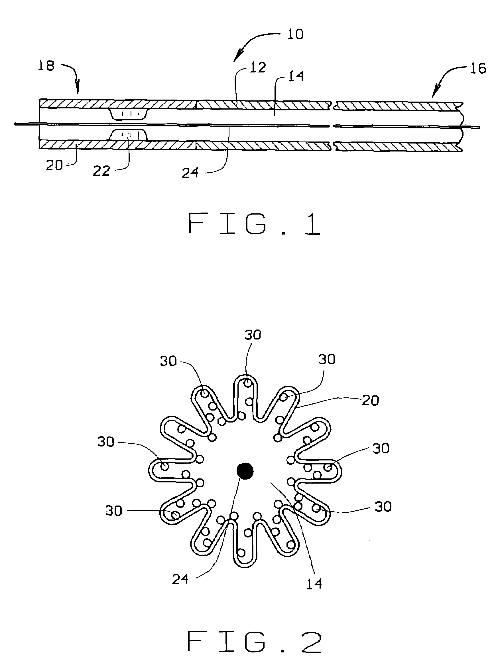
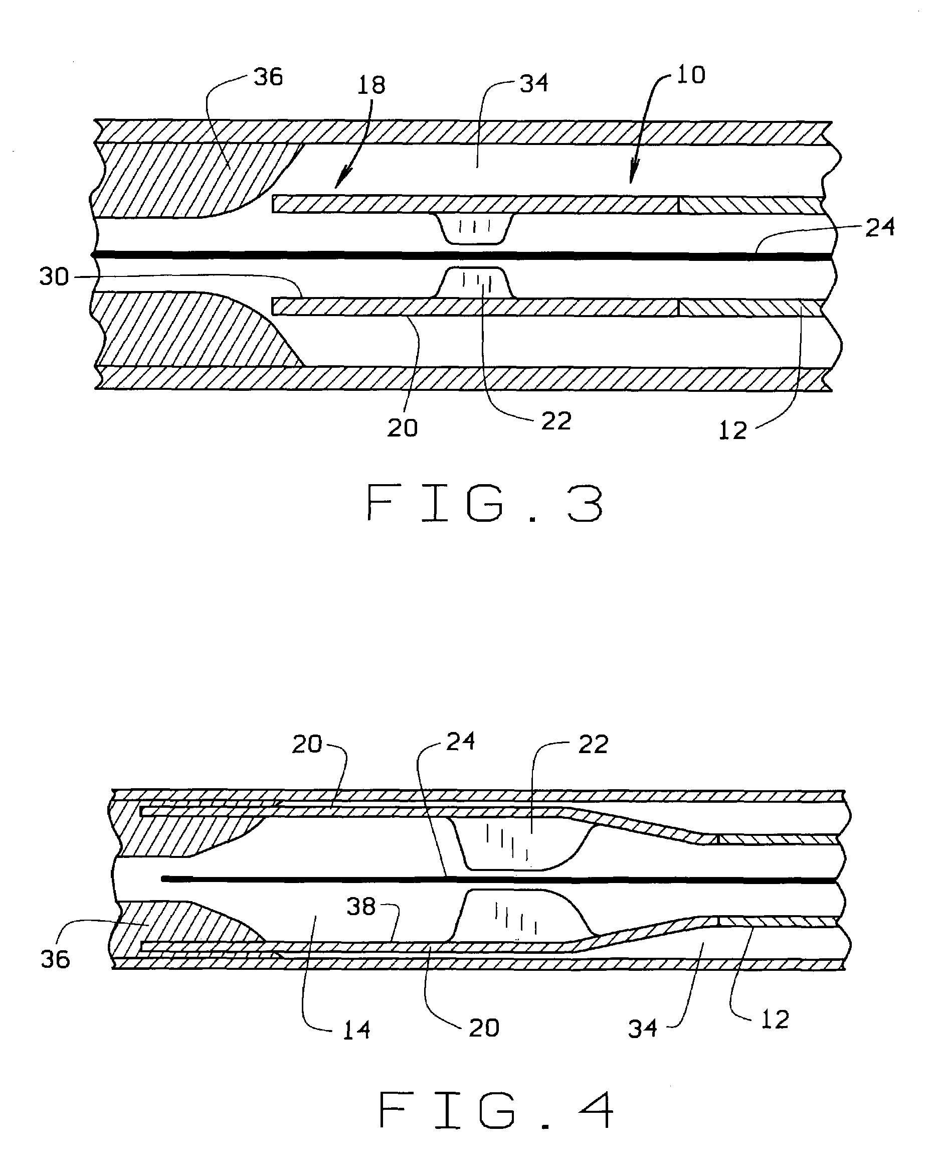
[0025]FIG. 1 is a sectional view of a laser catheter 10 in accordance with one embodiment of the present invention. Catheter 10 includes a shaftway 12 which defines a lumen 14 about a longitudinal axis, and has a proximal end 16, a distal end 18, and a flexible portion 20 adjacent distal end 18. Flexible portion 20 is configured in a plurality of folds having a radial orientation about the longitudinal axis of lumen 14. A ring-shaped inflatable balloon 22, or other means for expanding flexible portion 20, is attached to shaftway 12 within flexible portion 20. Balloon 20 may instead be attached to the guide wire or a mechanical device. Catheter 10 extends over a conventional guidewire 24. Balloon 22 is positioned from about 1 mm to about 10 mm behind the end of flexible portion 20. Balloon 22 communicates via air lines or tubing (not shown) as known in the art to a means for inflating the balloon, such as a syringe, air compressor or other air pressure providing device (not shown). M...


PUM


Abstract

Expandable laser catheters for utilizing laser energy to remove obstructions from body passages are described. In one embodiment, the laser catheter includes a shaftway having a distal end including a flexible portion configured in a series of radial folds. Multiple optical fibers, configured to transmit laser energy, extend along the shaftway and are attached to the flexible portion. An inflatable, ring-shaped balloon is attached to the catheter within the flexible portion. In use, the catheter is inserted into a body passage such as an artery, and advanced until the distal end is adjacent to an obstruction. The balloon is inflated to expand the flexible portion and to bring the optical fibers nearer the inner wall of the body passage. Laser energy is directed by the optical fibers toward targeted regions of the obstruction. As the catheter is advanced and the process repeated, a core is formed from the obstruction and contained within the flexible portion. The flexible portion is then contracted to hold the core, and the core is removed from the body passage by withdrawing the catheter.

Description

[0001]This application is a continuation of U.S. patent application Ser. No. 09 / 564,137, filed May 3, 2000, now U.S. Pat. No. 6,485,485, which is a divisional of U.S. patent application Ser. No. 09 / 133,575, filed Aug. 13, 1998, now U.S. Pat. No. 6,106,515. This application claims priority from U.S. patent application Ser. No. 09 / 564,137, filed May 3, 2000, now U.S. Pat. No. 6,485,485, which is a divisional of U.S. patent application Ser. No. 09 / 133,575, filed Aug. 13, 1998, now U.S. Pat. No. 6,106,515, both of which are hereby incorporated by reference.FIELD OF THE INVENTION[0002]This invention relates generally to laser catheters and more particularly, to an expandable laser catheter for removing obstructions from body passages.BACKGROUND OF THE INVENTION[0003]Atherosclerotic plaque is known to build up on the walls of arteries in the human body. Such plaque build-up restricts circulation and often causes cardiovascular problems, especially when the build-up occurs in coronary arte...

Claims


Application Information

Patent Timeline
IPC IPC(8): A61B18/18A61B17/22A61B18/22A61B18/24A61F2/958A61M25/00A61M29/02
CPCA61B18/245A61M25/0021A61M25/0023A61M29/02A61B18/24A61B2017/22051A61B2018/2211A61B2018/2266A61M2025/0024A61M2025/1004A61B2018/2288A61B2018/00214A61B2018/00577A61B2018/2238A61M25/1002
Inventor WINSTON, THOMAS R.NEET, JOHN M.
Owner SPECTRANETICS
Learn More