Three-phase cyclonic fluid separator with a debris trap

a cyclonic fluid separator and debris trap technology, which is applied in the direction of liquid degasification, lubricant mounting/connection, separation processes, etc., can solve the problems of not being retained by the collector, and the small particles often did not possess sufficient momentum

Active Publication Date: 2007-10-30
EATON INTELLIGENT POWER LIMITED
View PDF8 Cites 41 Cited by
  • Summary
  • Abstract
  • Description
  • Claims
  • Application Information

AI Technical Summary

Problems solved by technology

Small particles often did not possess sufficient momentum and thus were not retained by the collector.

Method used


Image

  • Three-phase cyclonic fluid separator with a debris trap
  • Three-phase cyclonic fluid separator with a debris trap
  • Three-phase cyclonic fluid separator with a debris trap

Examples


Embodiment Construction

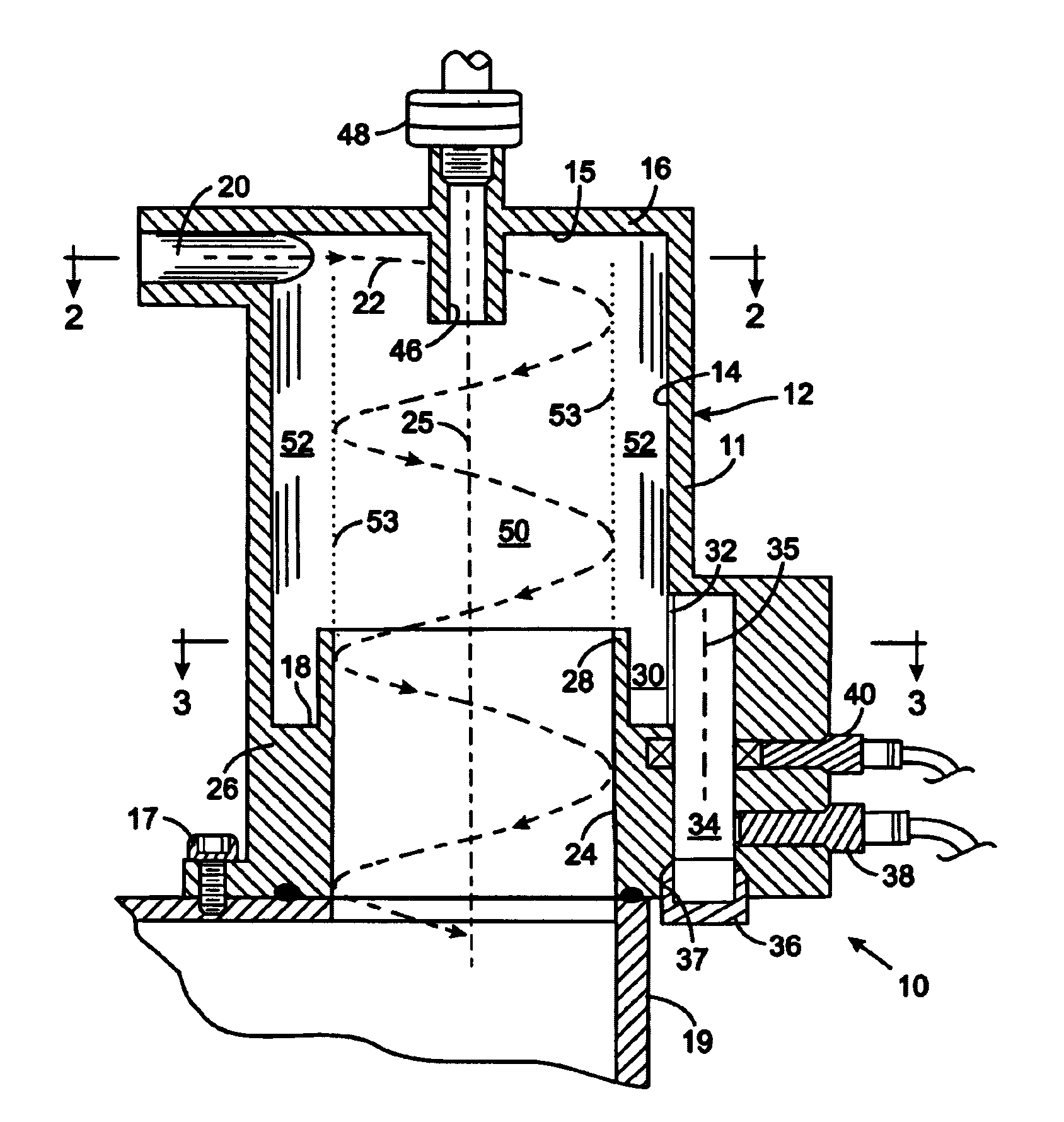
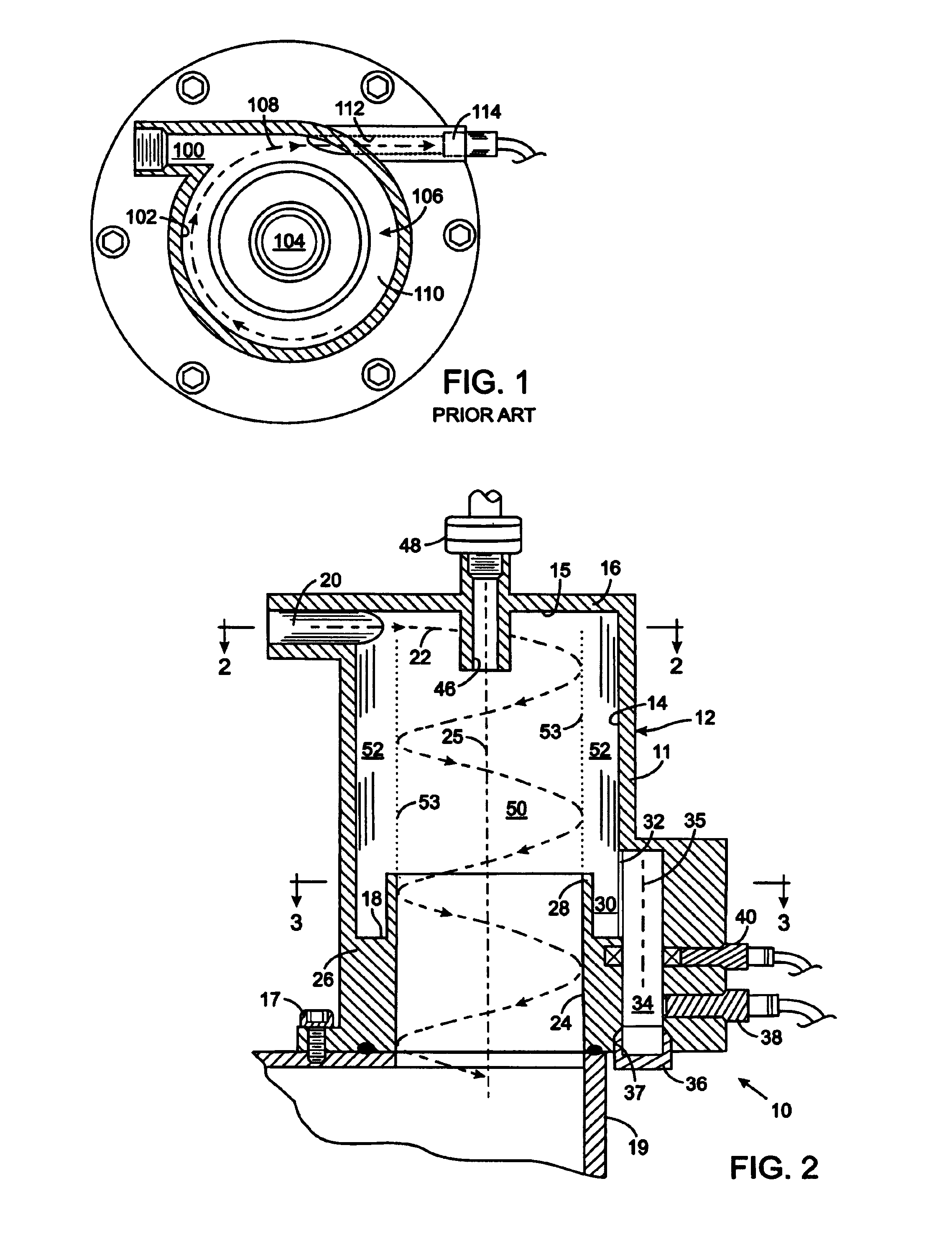
[0022]With initial reference to FIG. 2, a three-phase separator 10 is provided to separate liquid, gas and solid components from a mixture. Although the separator 10 has particular utility in an engine lubrication system, it should be appreciated that the separator can be employed in other types of fluid systems. The separator 10 comprises a housing 12 with a tubular, cylindrical side wall 11 extending between a first end wall 16 and a second end wall 26, thereby forming a circular cylindrical separation chamber 14 with a first, or top, end 15 and a second, or bottom, end 18. The housing 12 abuts a lubricant reservoir 19 of the lubrication system and is attached thereto by plurality of machine screws 17 or other fastening mechanism.

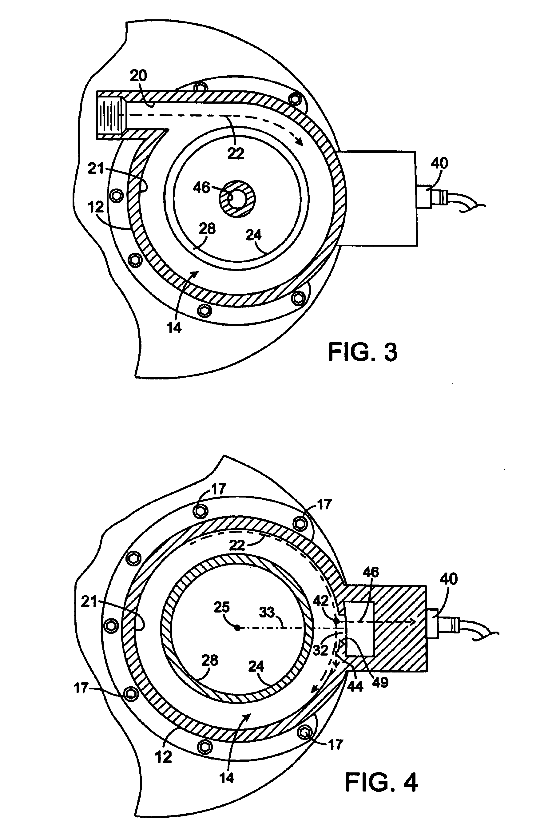
[0023]With additional reference to FIG. 3, an inlet 20 opens into the separation chamber 14 adjacent the first end wall 16 and is aligned tangentially with curved surface of the cylindrical separation chamber 14. As will be described, a mixture of materia...


PUM

PropertyMeasurementUnit
tangential velocityaaaaaaaaaa
radial velocityaaaaaaaaaa
magnetic probeaaaaaaaaaa

Abstract

An apparatus separates liquid, gas and solid components of a mixture in a fluid system. An inlet for receiving the mixture opens into a separation chamber tangentially with a cylindrical side wall and a gas outlet has an opening in a first end wall adjacent the inlet to allow gas to exit the separator. A fluid outlet is located in an opposing second end wall. A debris passage extends through the cylindrical side wall and oriented so that the radial velocity of the particles within the separation chamber directs the particles through the debris passage. The debris passage leads to a particle collection chamber in which the particles accumulate. Unlike prior separators that relied on the tangential velocity of the particles, the present apparatus utilizes the greater radial velocity to drive the particles from the separation chamber into the particle collection chamber.

Description

CROSS-REFERENCE TO RELATED APPLICATIONS[0001]Not ApplicableSTATEMENT REGARDING FEDERALLY SPONSORED RESEARCH OR DEVELOPMENT[0002]Not ApplicableBACKGROUND OF THE INVENTION[0003]1. Field of the Invention[0004]The present invention relates to devices for separating debris particles and gas from fluids in machinery, such as lubricants in an engine; and more particularly to such devices that perform the separation by creating a fluid vortex.[0005]2. Description of the Related Art[0006]Modern turbine engines, such as those used in aircraft, are lubricated by oil supplied to moving engine components by a pump that draws the oil from a reservoir. The oil flows from those components into sumps within the engine from which scavenger pumps force the fluid back to the reservoir. In the course of flowing through the engine, the oil often picks up metal and non-metal debris particles and also becomes aerated due to a turbulent flow. Therefore, it is common practice for this mixture to pass through...

Claims


Application Information

Patent Timeline
Patent Type & Authority Patents(United States)
IPC IPC(8): B01D19/00
CPCB01D21/0009B01D21/245B01D21/2494B01D21/30B04C5/14B04C5/185B04C9/00B04C11/00B01D21/2411B01D21/267B01D21/26B01D2221/08B01D21/0006B03C1/286B03C2201/18B03C2201/24B03C2201/28
Inventor SHOWALTER, STEPHEN
Owner EATON INTELLIGENT POWER LIMITED
Why Eureka
Try Eureka