Multi-core optical fiber image amplifier and method of drawing

a multi-core, optical fiber technology, applied in the direction of optical elements, bundled fibre light guides, instruments, etc., can solve the problems of limiting reducing the original phase information, and affecting the performance of the amplifier, so as to achieve high-gain effects

Active Publication Date: 2007-10-30
NP PHOTONICS A CORP OF DELAWARE
View PDF8 Cites 39 Cited by
  • Summary
  • Abstract
  • Description
  • Claims
  • Application Information

AI Technical Summary

Benefits of technology

The present invention is about an optical image amplifier that produces high-quality images with low noise. This invention has a high gain, which means it can amplify the image signals effectively.

Problems solved by technology

The technical problem addressed in this patent text is the need for a more efficient and effective method for amplifying optical images without losing the phase or spectrum of the incident light field. Current methods such as electronic amplification and microchannel plates have limitations such as noise and the need for O-E-O conversion. Wave mixing and coherent passive fiber bundles have been proposed as alternative methods, but they also have limitations such as the need for high-power beams and the need for precise alignment.

Method used


Image

  • Multi-core optical fiber image amplifier and method of drawing
  • Multi-core optical fiber image amplifier and method of drawing
  • Multi-core optical fiber image amplifier and method of drawing

Examples


Embodiment Construction

[0021]The present invention provides a low-noise, high-gain optical image amplifier that avoids the noise and loss of spectrum and phase information associated with O-E-O conversion.

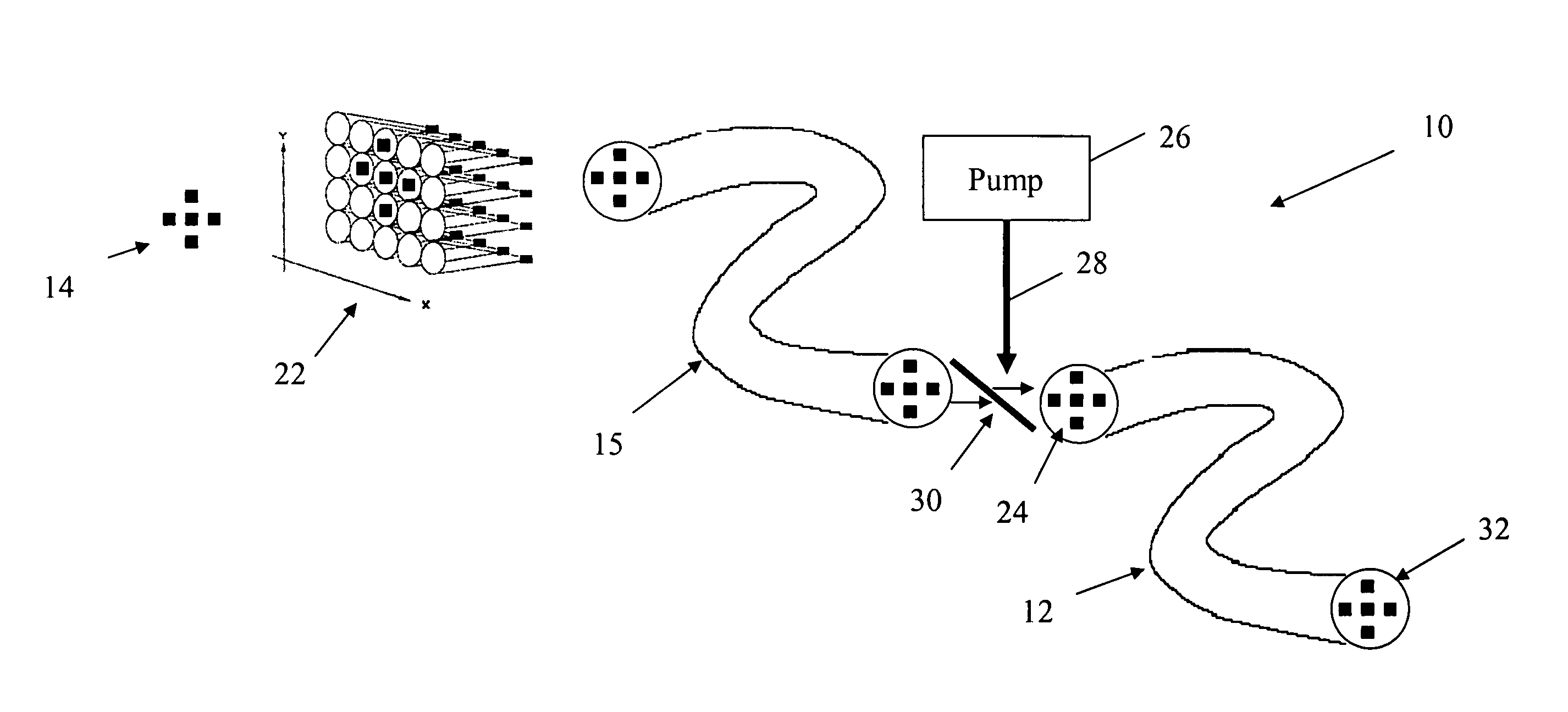
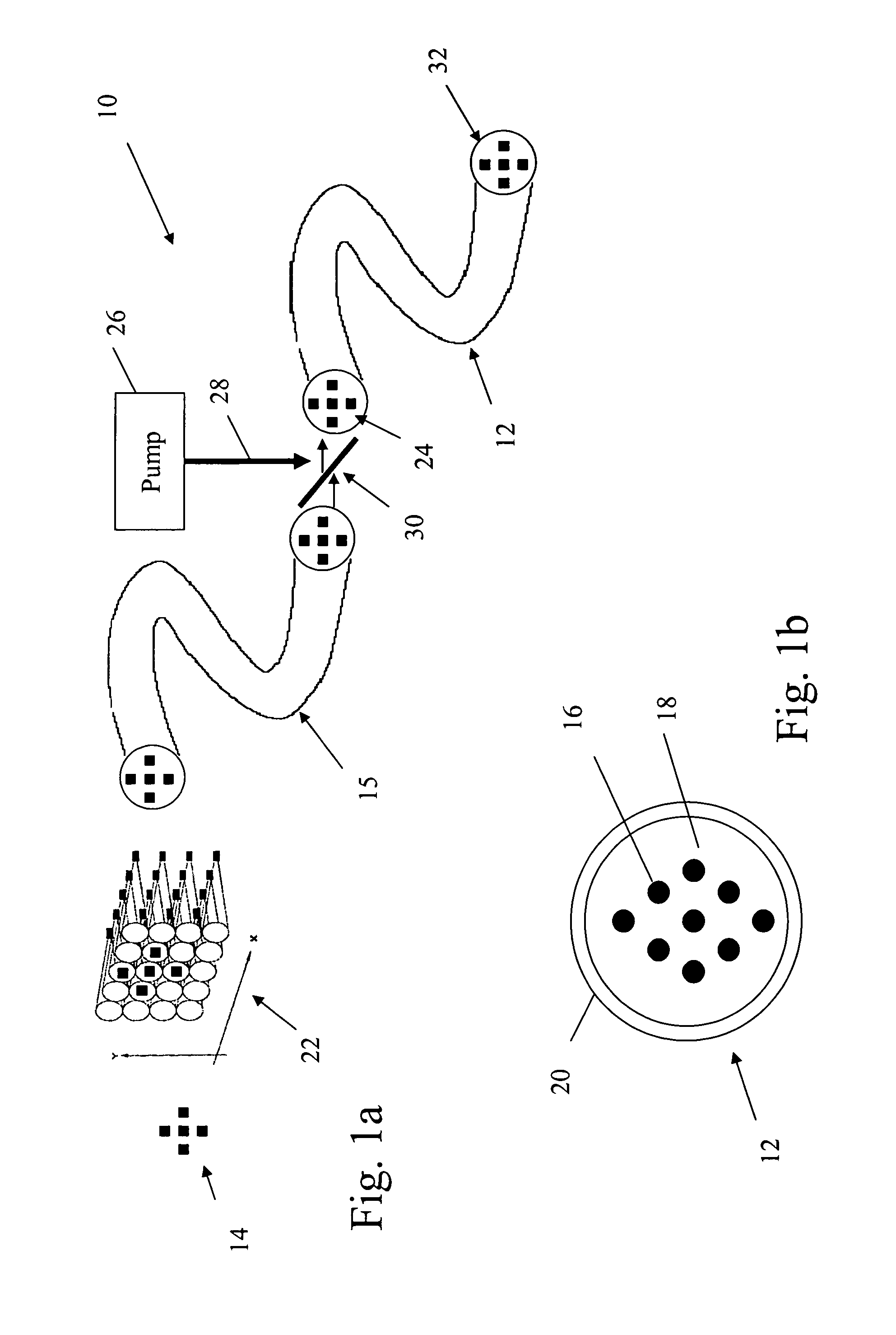
[0022]As shown in FIGS. 1a and 1b, a fiber image amplifier 10 includes a multi-core active fiber 12 that optically amplifies an incident image 14. Direct optical amplification preserves the spectrum of the incident image, is lower noise and can be configured to preserve phase information if desired. Active fiber 12 includes a plurality of doped cores 16 arranged in a 2-D array inside an inner cladding 18, which is inscribed in an outer cladding 20. To amplify an “image”, the 2-D array will typically include at least 9 doped cores.

[0023]Active fiber 12 is suitably optically coupled to a passive transport fiber 15. In this embodiment, a lenslet array 22 samples and collects light from image 14 into transport fiber 15, which in turn transports the pixilated image 24 to the active fiber. The transport fiber ...


PUM


Abstract

A low-noise, high-gain optical image amplifier includes a multi-mode pump source that injects optical energy into an active fiber's inner cladding to excite the dopant ions in a 2-D array of doped cores and provide gain. The cores are arranged to sample and collect light from an image incident on one end of the fiber, amplify the light and output an amplified pixilated image at the other end of the fiber. The multi-core active fiber preserves the spatial pattern and spectrum of the incident image. The cores may be configured as single-mode cores to preserve phase information or multi-mode cores to scramble the phase information. It is often desirable for the gain to be approximately uniform across the 2-D array. This can be achieved by pumping uniformly doped cores into their respective saturation regions.

Description


Claims


Application Information

Patent Timeline
Owner NP PHOTONICS A CORP OF DELAWARE
Why Eureka
Try Eureka