Combined solar powered fan and hat arrangement for maximizing airflow through the hat

Active Publication Date: 2007-11-06
NELLON TOMMIE L
View PDF9 Cites 26 Cited by
  • Summary
  • Abstract
  • Description
  • Claims
  • Application Information

AI Technical Summary

Benefits of technology

[0011]In view of the foregoing background, it is therefore an object of the present invention to provide a combined solar powered fan and hat arrangement for maximizing airflow through the hat. These and other objects, features, and advantages of the invention are provided by an apparatus for protecting a user's head from undesirable UV light while ventilating stagnant air emanating from a user's head.
[0012]The apparatus includes a hat formed from straw material and including a unitary and continuous brim that has an annular shape. Such a brim is provided with radially spaced inner and outer edges wherein the inner edge is positioned above the outer edge for effectively defining a smooth slope traveling downwardly and outwardly towards the outer edge. The hat further includes a raised head region monolithically formed with the inner edge of the brim. Such a head region has a pair of spaced apex regions equidistantly offset from a centrally registered longitudinal axis that bifurcates the hat. The apex regions are coextensive and extend along a longitudinal length of the head region. Such a head region further has a rectilinear trough intercalated between the apex regions and monolithically formed therewith. The trough effectively channels humid and stagnant air upwardly towards the apex regions for advantageously maximizing a vertical separation between the user's head and the head region of the hat.
[0013]The hat has an oblong opening formed within the head region in which the opening is sized and shaped for effectively allowing air to flow outwardly from the hat region at a rate equal to at least twice an inlet air flow rate of the motorized fan. Such an opening is disposed at a rear of the hat region and centrally registered between the apex regions.
[0015]The motorized fan is further preferably situated to an exterior of the hat and is diametrically opposed from the opening in such a manner that a continuous and unobstructed path is effectively defined between the motorized fan and the opening. Such a motorized fan may further be horizontally registered with the opening. A plurality of flat solar panels are directly connected to a top surface of the brim and equidistantly spaced adjacent to the outer edges for effectively absorbing a maximum quantity of light rays emitting from above.

Problems solved by technology

Although this design may relieve the person to a certain extent, and prevent sweat from running into their eyes, it is not the most optimal design for a maximal cooling effect.
For this reason, runners are advised not to wear a hat when running because the heat generated by their bodies can not escape from under the hat, which may lead to excessive sweating and subsequently, heat exhaustion or heat-stroke.
Such fans are usually of a flimsy plastic design that is not sufficient for creating a significant amount of airflow over an extended period of time.
Furthermore, the blades of the fans tend to be easily bent or broken, thus rendering the cooling means ineffective or useless.

Method used


Image

  • Combined solar powered fan and hat arrangement for maximizing airflow through the hat
  • Combined solar powered fan and hat arrangement for maximizing airflow through the hat
  • Combined solar powered fan and hat arrangement for maximizing airflow through the hat

Examples


Embodiment Construction

[0023]The present invention will now be described more fully hereinafter with reference to the accompanying drawings, in which a preferred embodiment of the invention is shown. This invention may, however, be embodied in many different forms and should not be construed as limited to the embodiment set forth herein. Rather, this embodiment is provided so that this application will be thorough and complete, and will fully convey the true scope of the invention to those skilled in the art. Like numbers refer to like elements throughout the figures.

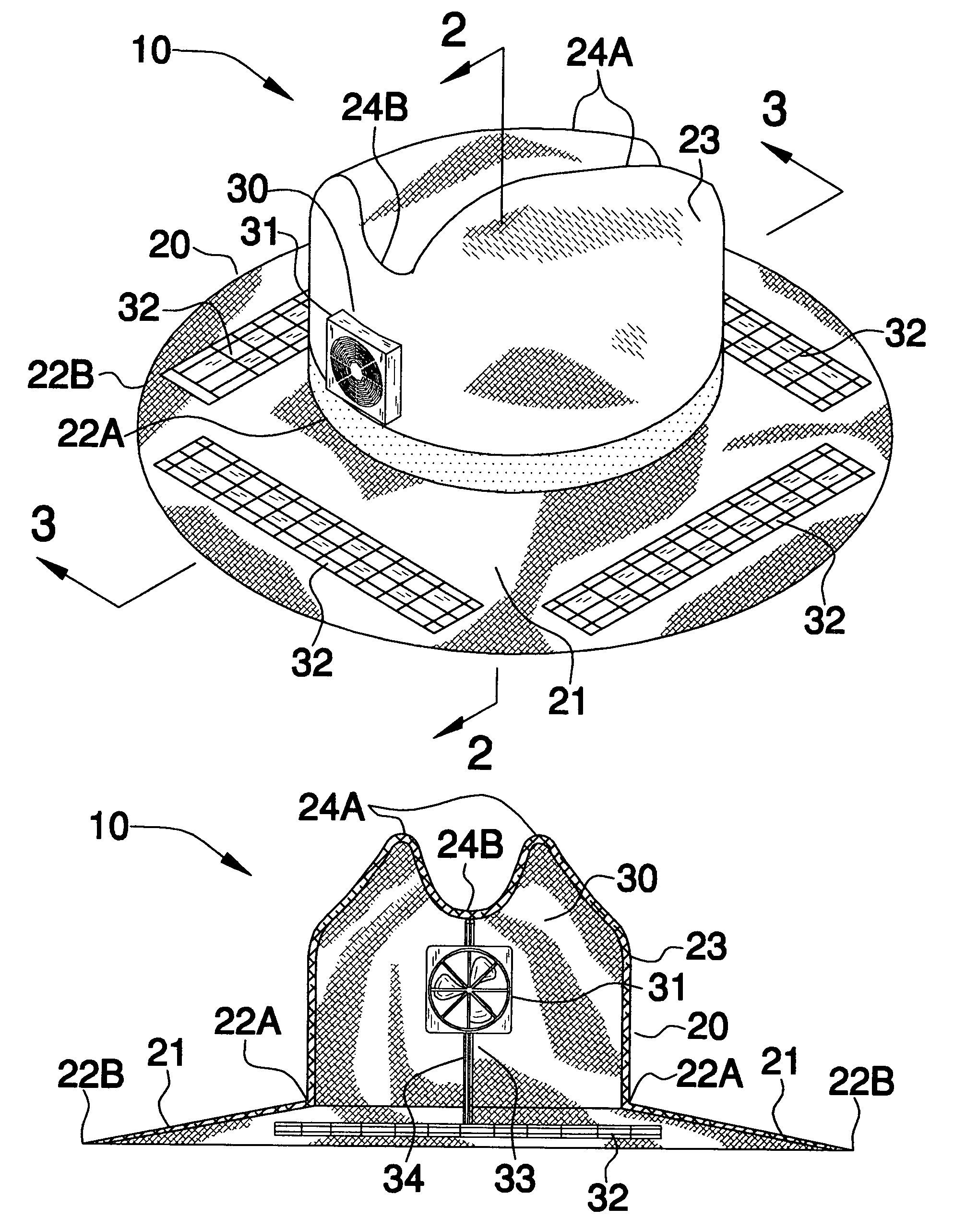
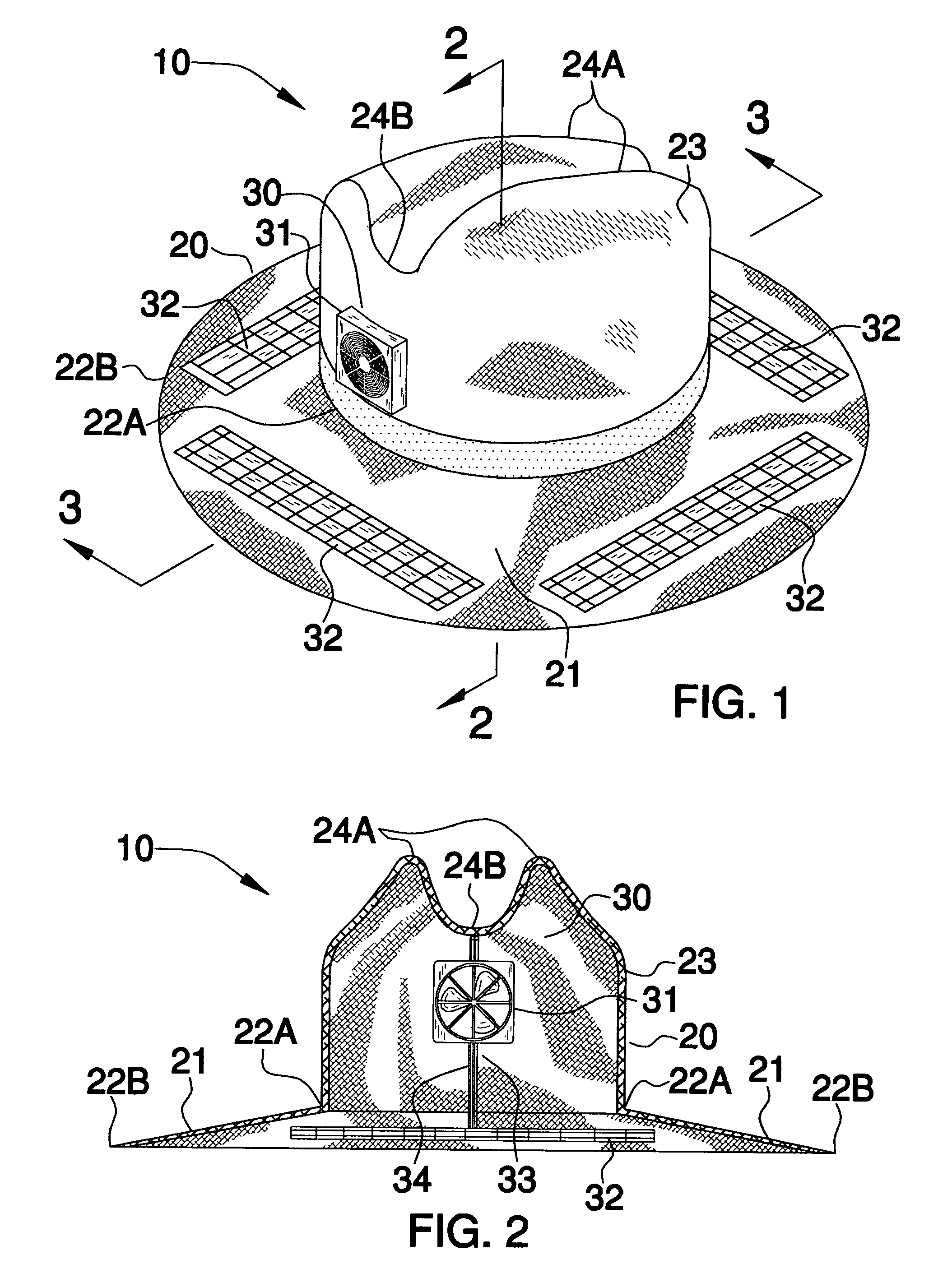
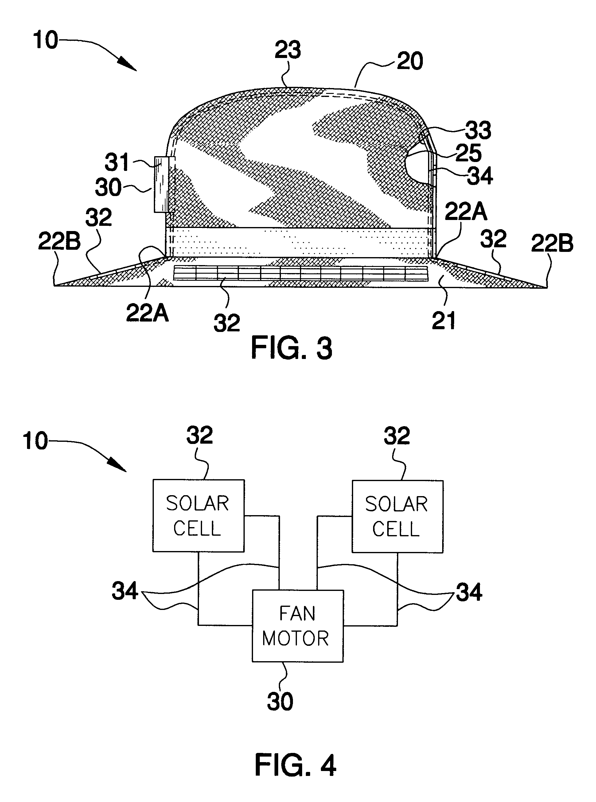
[0024]The apparatus of this invention is referred to generally in FIGS. 1-4 by the reference numeral 10 and is intended to provide a combined solar powered fan and hat arrangement for maximizing airflow through the hat. It should be understood that the apparatus 10 may be used to provide improved airflow in many different types of hats and should not be limited in use to only wide brim straw hats.

[0025]Referring initially to FIG. 1, the appar...


PUM


Abstract

An apparatus includes a hat including a unitary brim that is provided with spaced inner and outer edges defining a slope traveling downwardly and outwardly towards the outer edge. The hat further includes a raised head region including a pair of spaced and coextensive apex regions and a trough intercalated therebetween. The hat has an oblong opening disposed at the rear of the head region for allowing air to flow outwardly from the head region at a rate equal to at least twice an inlet air flow rate. A motorized fan is mounted to a front side of the head region and subjacent to the trough. Solar panels are connected to a top surface of the brim. A sleeve is formed along an interior surface of the hat that extends from the solar panels and is connected to the fan for housing electrical leads coupled thereto.

Description

CROSS REFERENCE TO RELATED APPLICATIONS[0001]Not Applicable.STATEMENT REGARDING FEDERALLY SPONSORED RESEARCH OR DEVELOPMENT[0002]Not Applicable.REFERENCE TO A MICROFICHE APPENDIX[0003]Not Applicable.BACKGROUND OF THE INVENTION[0004]1. Technical Field[0005]This invention relates to hats and, more particularly, to a combined solar powered fan and hat arrangement for maximizing airflow through the hat.[0006]2. Prior Art[0007]Many sports fans have experienced the enjoyment of watching an outdoor sporting event while suffering the effects of high heat and humidity. In an attempt to overcome this problem, various hats or caps have been designed to include fans powered by a motor. The power source for the motor of the fan has included either solar power, electric battery power, or the choice of using either solar power or electric battery power. These hats include two separate components, with the power source usually being on top or inside the hat and with the fan usually located in the t...

Claims


Application Information

Patent Timeline
IPC IPC(8): A42C5/04
CPCA42C5/04
Inventor NELLON, TOMMIE L.
Owner NELLON TOMMIE L
Why Eureka
Try Eureka