
Drinking water cooler

Inactive Publication Date: 2012-07-26
TECH APPL
View PDF3 Cites 0 Cited by
  • Summary
  • Abstract
  • Description
  • Claims
  • Application Information

AI Technical Summary

Benefits of technology

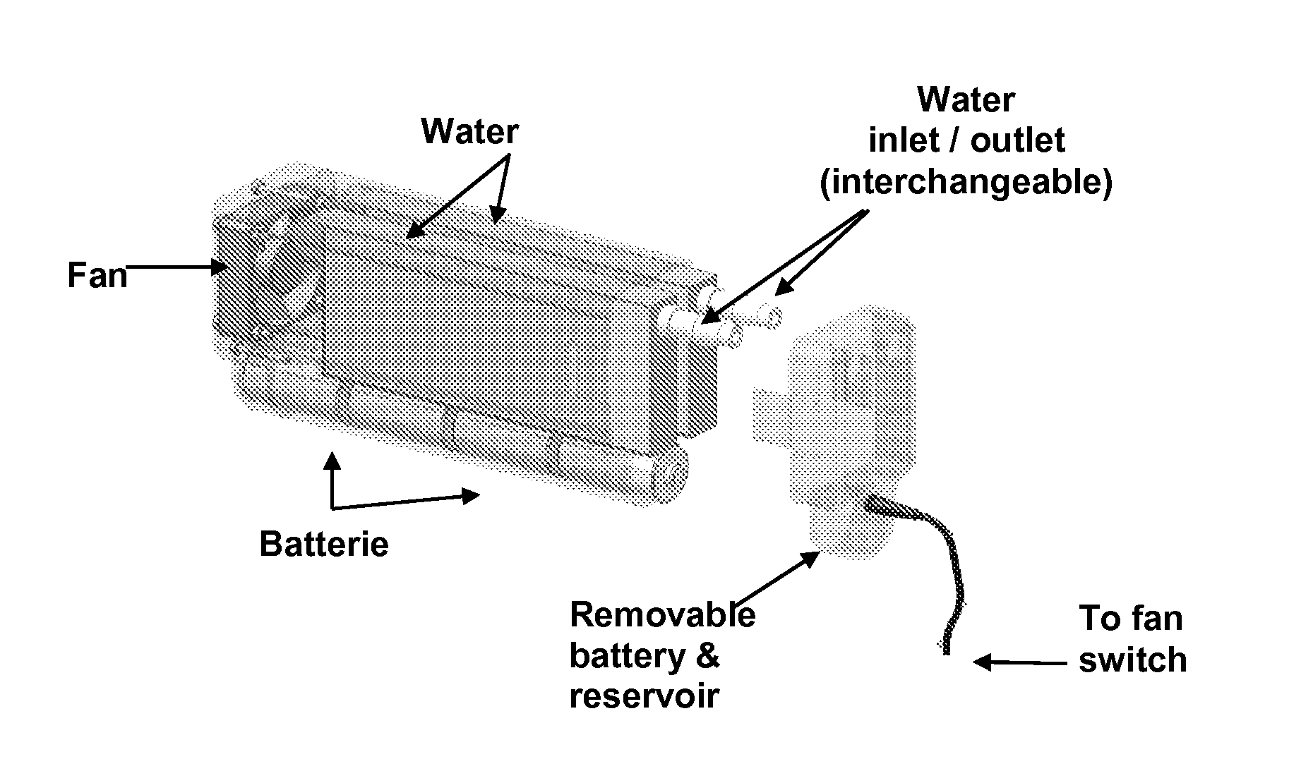
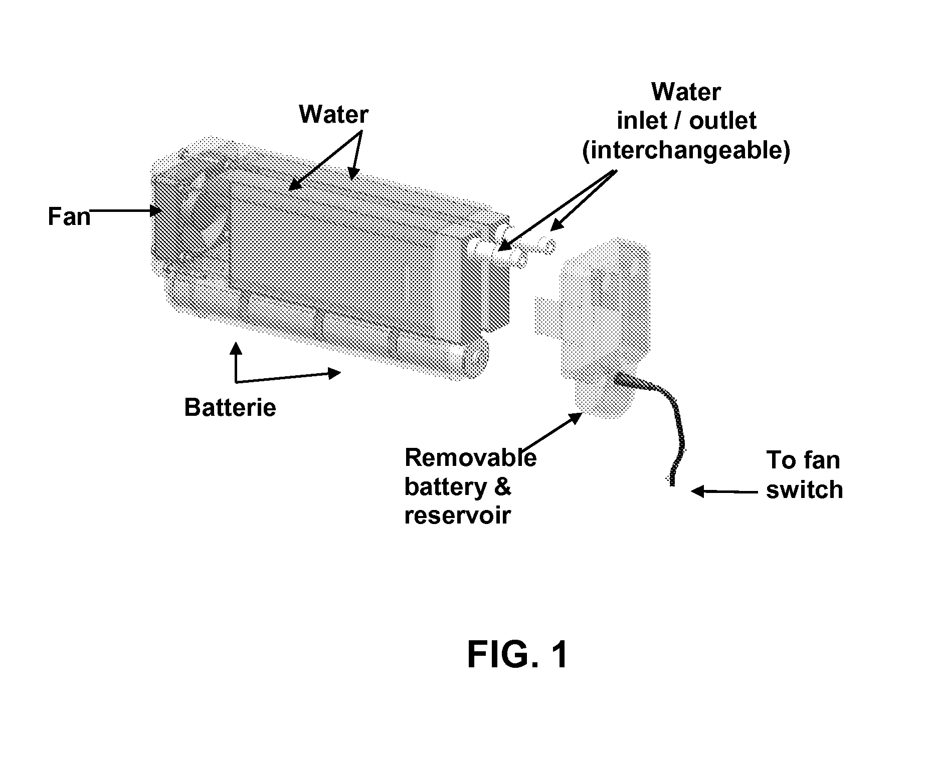
[0008]In an aspect of the invention, the system further comprises a housing surrounding the one or more liquid reservoirs. In an aspect of the invention, there is an exterior housing which holds the reservoirs / evaporative elements, fan, and fan power source (sources include batteries and / or solar panel(s)) and protects the reservoirs / evaporative elements. In an embodiment this housing also defines the airflow channel geometry with the shape of its inner surfaces. In an aspect of the invention, these airflow channels are shaped such that pressure drop through the airflow channels is minimized, which maximizes the airflow provided by the fan.
[0013]In an aspect of the invention, the liquid reservoir contains one or more a baffles or internal ribs positioned to direct the liquid flow through the liquid reservoir. This aspect prevents liquid which is warm as compared to the cooled liquid from flowing directly from the inlet and outlet and allows sufficient residence time in the device for the desired cooling. The baffle or internal rib may occupy any suitable area of the liquid reservoir. In a specific embodiment of this aspect of the invention, in a generally rectangular liquid reservoir, the baffle is positioned approximately half way on the height of the reservoir and extends less than the full length of the reservoir. In an embodiment of this aspect of the invention, the baffle is an integral part of the reservoir (i.e., the reservoir and baffle are one piece). In an embodiment of this aspect of the invention, the baffle is attached to the reservoir using any suitable method, such as glue, thermal bonding, or other method known to one of ordinary skill in the art without undue experimentation.
[0014]In an embodiment where there is more than one liquid reservoir, the liquid reservoirs are attached together in any suitable method using any suitable material. In an aspect of the invention, the liquid reservoirs are attached together using a tube. In an aspect of the invention, the liquid reservoirs are attached together using a flange or other aspect which is positioned on each liquid reservoir at an opposite end from the liquid inlet or outlet. This flange or other attachment means can be any suitable material, such as metal, plastic, polymer, or other material which are suitable for the desired purpose. When there is more than one reservoir in an aspect of the invention, the liquid flow between the reservoirs can be designed to minimize the air present in the reservoirs.
[0024]In an aspect of the invention, the system further comprises airflow channels on one or both sides of the reservoir and / or evaporative elements. These airflow channels may be provided by a housing, in one embodiment. The airflow channels may also be fabricated into the reservoir and / or evaporative elements. In an aspect of the invention, the airflow channels are sized and scaled to meet water / liquid cooling / consumption requirements. In an aspect of the invention, there is a screen or filter positioned adjacent to an evaporative element to prevent fouling of the evaporative element. This is particularly useful in an environment where there is no housing.

Problems solved by technology

Poor hydration affects multiple body systems.
Although the importance of hydration is known, it is usually less appealing to drink warm liquids as the ambient temperature rises.
Insulation has been used to slow warming of liquids in containers, but is ineffective for long periods of time.

Method used


Image

  • Drinking water cooler
  • Drinking water cooler
  • Drinking water cooler

Examples


Embodiment Construction

[0046]In general, the terms and phrases used herein have their art-recognized meaning, which can be found by reference to standard texts, journal references and contexts known to those skilled in the art. As to the embodiments of the invention, it is understood that any embodiment having a combination of components which is not able to be made is not included in the invention. Although Applicant does not wish to be bound by theory, the description herein is provided to aid in understanding of the invention. The following description is provided to illustrate specific embodiments of the invention. It is understood that all aspects of the invention which are described using a specific embodiment or embodiments referred to in the alternative (one or more liquid reservoirs, for example) are applicable to other embodiments and are intended to be disclosed herein to the same extent as if they were specifically listed.

[0047]As will be appreciated, the drinking water cooler can have a varie...


PUM


Abstract

A liquid cooling system comprising: a liquid inlet and outlet; one or more liquid reservoirs in fluid communication with the liquid inlet and outlet; an evaporative element in fluid communication with a liquid reservoir; and a fan in flowable communication with a surface of the evaporative element is provided. The liquid cooling system can cool drinking water. The liquid cooling system can be powered by AC power, DC power, solar power or a combination. The liquid cooling system can be used in-line in a hydration system, for example.

Description

CROSS-REFERENCE TO RELATED APPLICATIONS[0001]This application claims priority to U.S. provisional patent application Ser. No. 61 / 181,943, filed May 28, 2009, which is incorporated by reference in its entirety.STATEMENT REGARDING FEDERALLY SPONSORED RESEARCH OR DEVELOPMENT[0002]This invention was made with government support under grant M67854-08-C-6511, awarded by the Department of the Navy. The government has certain rights in the invention.BACKGROUND OF THE INVENTION[0003]Proper hydration is important for general health, as well as for improving athletic performance. Poor hydration affects multiple body systems. Although the importance of hydration is known, it is usually less appealing to drink warm liquids as the ambient temperature rises. Insulation has been used to slow warming of liquids in containers, but is ineffective for long periods of time.[0004]A device to cool drinking water that is small and lightweight, cools water to below ambient temperature, can be retrofitted wi...

Claims


Application Information

Patent Timeline
IPC IPC(8): F28D5/00F25B27/00
CPCA45F3/04F25D7/00A45F3/20
Inventor BAUMGARTNER, ROLF GERALDHARMON, CHARLES JOSEPHSIEVERS, RYAN ANDREWWILLEN, GARY SCOTT
Owner TECH APPL
Learn More