Pneumatic nail gun

a nail gun and pneumatic technology, applied in the field of pneumatic nail guns, can solve the problems of reducing the speed and efficiency of nail punching, reducing the speed and efficiency of nailing, and limiting the collection of high pressure air in the air chamber for upward movement of the piston

Inactive Publication Date: 2007-11-06
DE POAN PNEUMATIC
View PDF12 Cites 55 Cited by
  • Summary
  • Abstract
  • Description
  • Claims
  • Application Information

AI Technical Summary

Benefits of technology

[0007]The pneumatic nail gun utilizes the upper and the lower slidable sleeve valves to realize the stably upward movement of the piston throug

Problems solved by technology

However, the air chamber just can receive the high pressure air when the piston moves downward and can not receive high pressure air during the piston moves upward.
Thus, the collection of the high pressure air in the air chamber for upward movement of the piston is limit

Method used


Image

  • Pneumatic nail gun
  • Pneumatic nail gun
  • Pneumatic nail gun

Examples


first embodiment

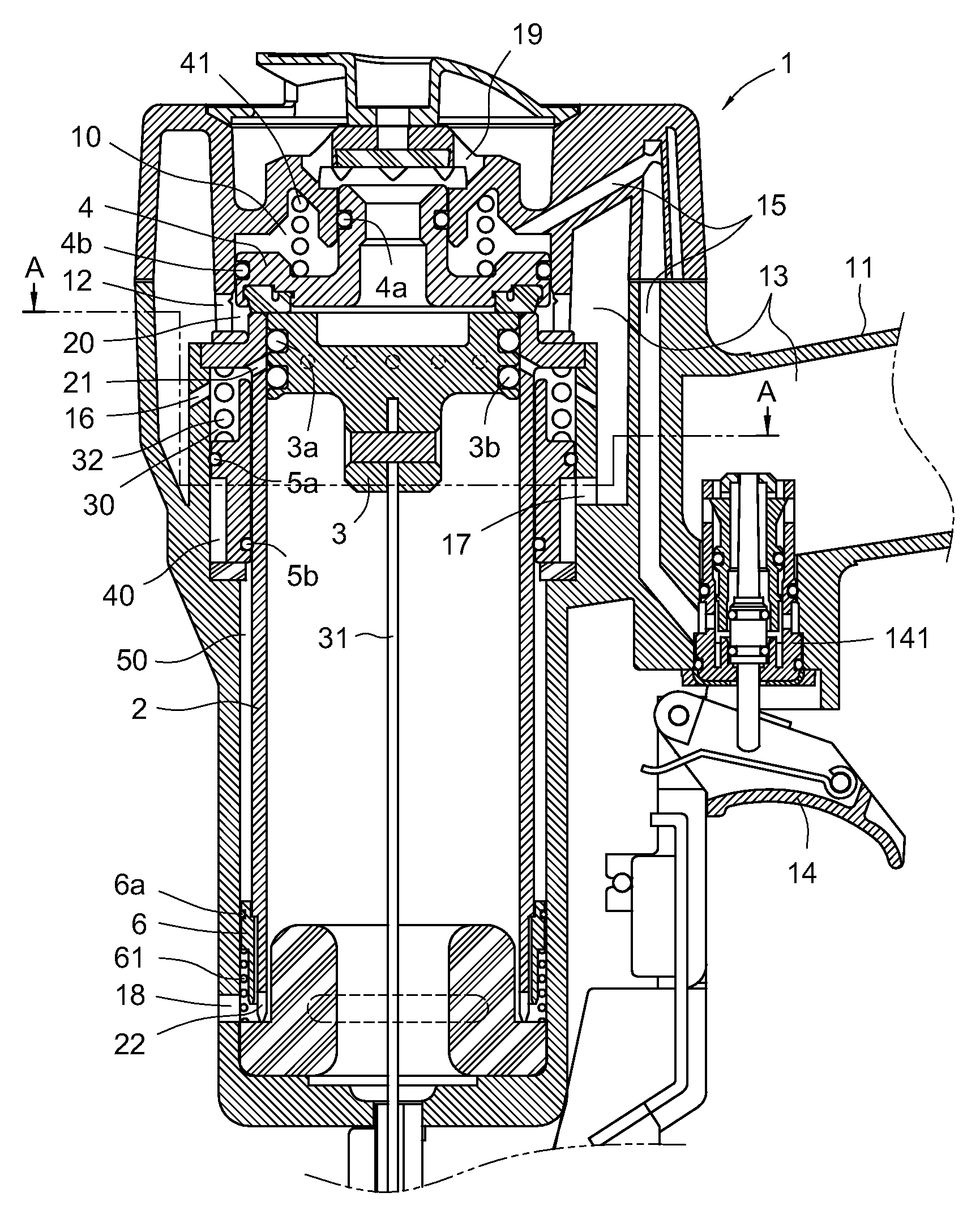
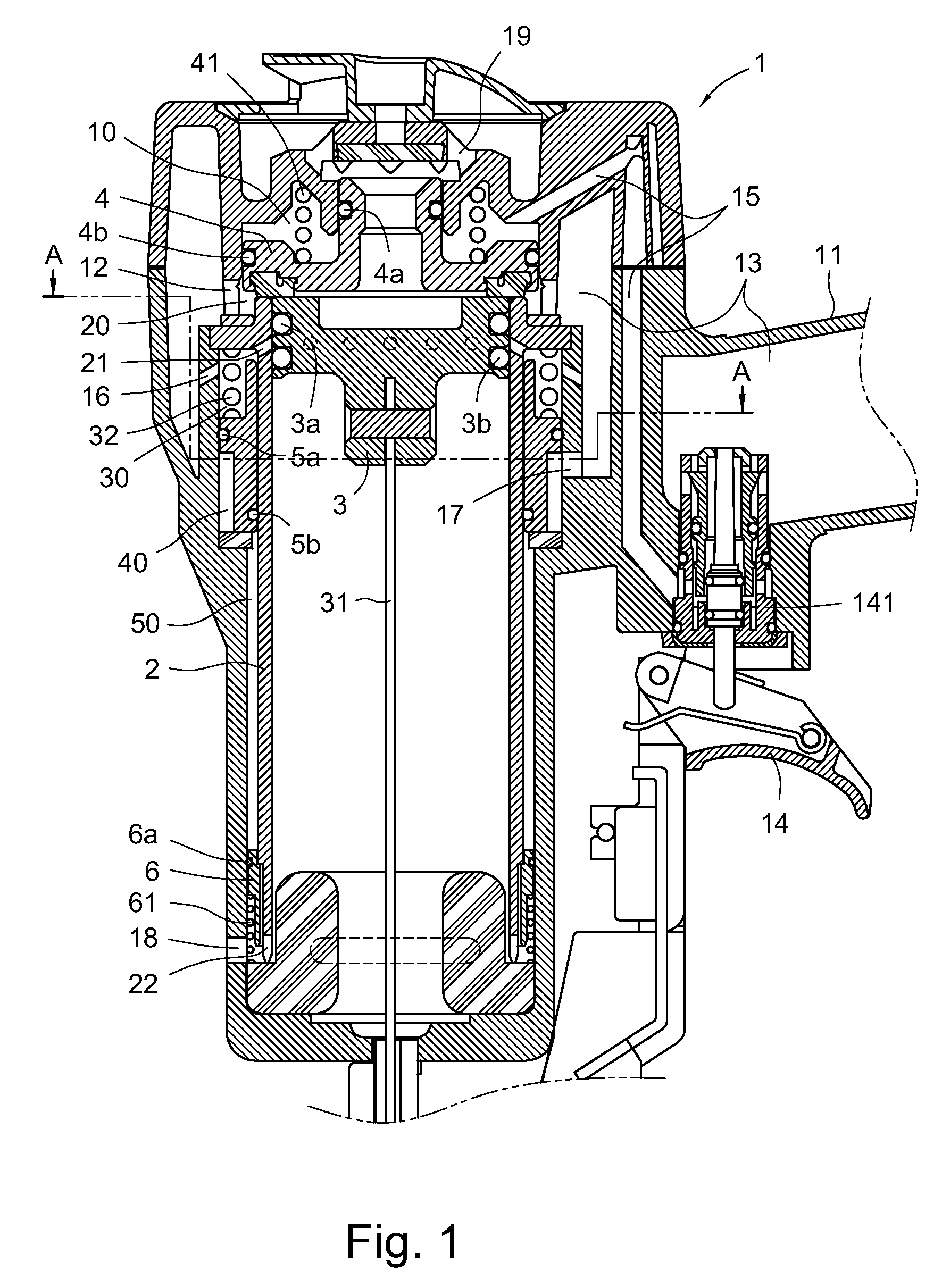
[0021]Referring to FIG. 1, a pneumatic nail gun according to the present invention is shown. The pneumatic nail gun has a gun body 1, an immovable cylinder 2, a hitting piston 3, a dish-shaped piston 4, an upper slide sleeve valve 5 and a lower slide sleeve valve 6.

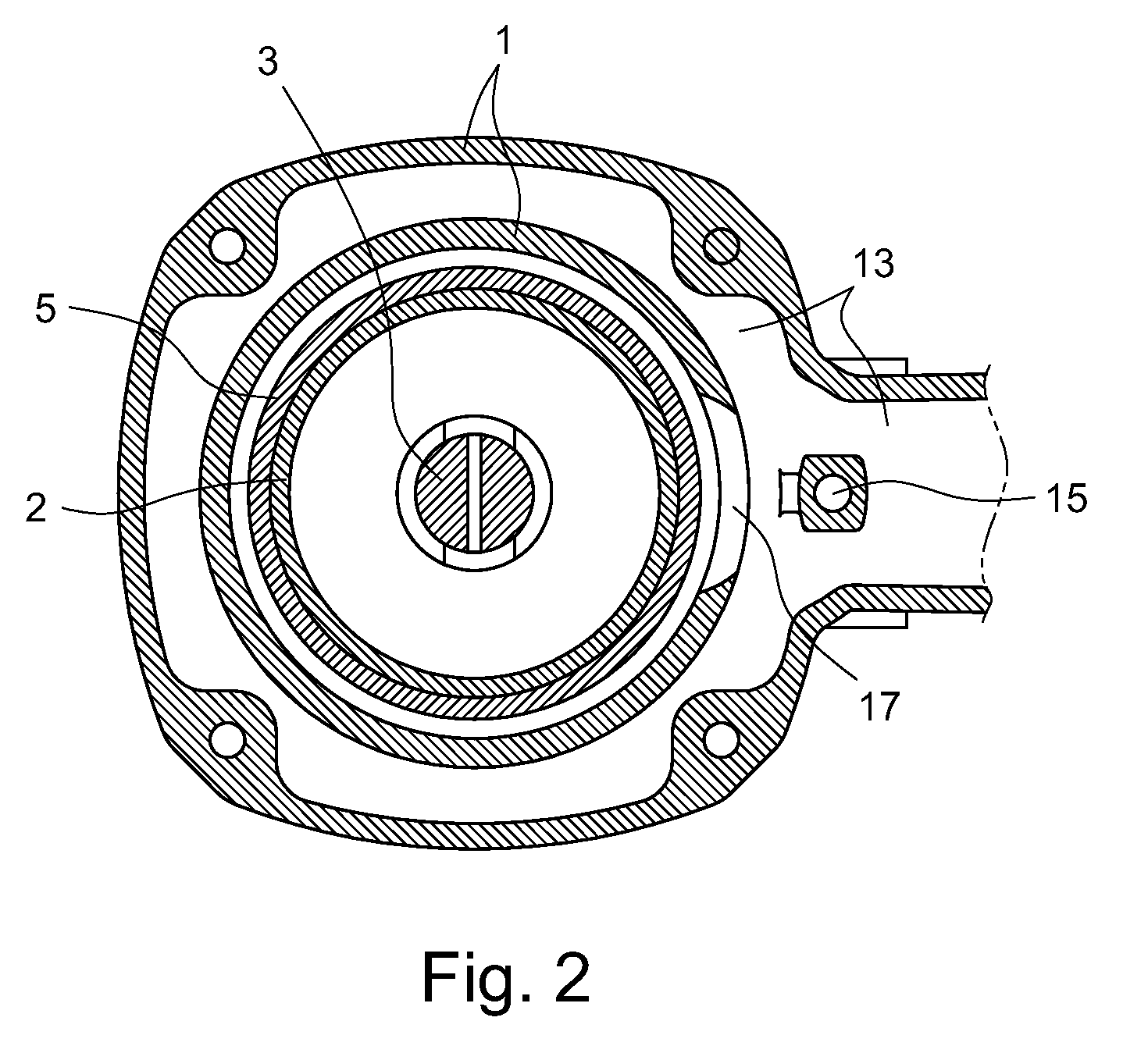
[0022]The gun body 1 has a main air housing 13 formed in a gun handle and gun head, which communicate with each other, for coutinuously collecting a compressed high-pressure air therein (as shown in FIG. 2). The gun body 1 further has a trigger 14 at one end of the main air housing 13, and a trigger valve 141 is disposed in the main air housing 13 to be operated by the manipulation of the trigger 14. The trigger valve 141 provides a first valve position by the non-manipulation to the trigger 14 to fluidly communicate the main air housing 13 and a first air chamber 10 in the gun body 1 with the high pressure air, and provides a second valve position by manipulation to the trigger 14 to shut off the fluid communication betw...

third embodiment

[0044]According to a pneumatic nail gun of third embodiment, a lower slidable sleeve valves 6 can utilize at least one upper step 62 formed at a top portion thereof and a lower step 63 formed at a lower portion thereof to replace the spring (as shown in FIG. 11). The upper step 62 has a forcing area A1 larger than that of a forcing area A2 of the lower step 63 (as shown in FIG. 12). The upper step 62 are pushed by the high pressure air from the fourth air chamber 40 or from the ring groove 50 which guides the high pressure air from the fourth air chamber 40. The lower step 63 are pushed by the high pressure air from a main air passage 60 formed in the gun body 1, which guides the high pressure air in the fourth air chamber 40. The lower slidable sleeve valve 6 further provides two air-tight rings 6a, 6b between its outer peripheral surface and the inner surface of the gun body 1. The lower step 63 and an entrance of the main air passage 60 are disposed between the two air-tight ring...


PUM

PropertyMeasurementUnit
Timeaaaaaaaaaa
Forceaaaaaaaaaa
Pressureaaaaaaaaaa

Abstract

A pneumatic nail gun has a gun body having a main air housing; a cylinder fixed in the main air housing; a hitting piston slidably movable in the cylinder; a dish-shaped piston disposed at a top end portion of the cylinder; an upper slidable sleeve valve disposed at a top portion of an out peripheral surface of the cylinder, which is driven to move upward by the high pressure air in the main air housing; and a lower slidable sleeve valve disposed at a lower portion of an outer peripheral surface of the cylinder, which is driven to move downward for guiding the high pressure air into the cylinder for upward deposition of the hitting piston when the upper slidable sleeve valve moves upward, and is driven to upward reposite when the hitting piston moves to its upper dead center.

Description

BACKGROUND[0001]The present invention relates to a pneumatic nail gun, and particularly to a pneumatic nail gun having an upper slidable sleeve valve and a lower slidable sleeve valve.[0002]The pneumatic nail gun generally utilizes a compressed high pressure air to drive nails to punch, which is a gun-shaped pneumatic tool. The general structure and function of a nail gun is briefly introduced as follows. A nail gun has a gun body, the gun body having a gun handle and a gun head; a fastening cylinder disposed in the gun head; a high-pressure gas pipe coupled to one end of the gun handle, and a high-pressure gas being input and introduced into the cylinder; a piston disposed in the cylinder, the piston connected to a nail shooting mechanism at the external end of the gun head, and the nail shooting mechanism coupled to a nail magazine. When the gun body is triggered, and the piston is pushed downward by the compressed high pressure air such that the nail shooting mechanism can shoot ...

Claims


Application Information

Patent Timeline
IPC IPC(8): B25C1/04
CPCB25C1/041
Inventor WEN, WAN-FU
Owner DE POAN PNEUMATIC
Why Eureka
Try Eureka