Retracting mechanism of vehicular outer mirror device

a technology of outer mirror and retracting mechanism, which is applied in the direction of machine supports, instruments, gear, etc., can solve the problems of abnormal noise, achieve excellent effects, prevent abnormal noise, and stably couple the output sha

Inactive Publication Date: 2007-11-06
KK TOKAI RIKA DENKI SEISAKUSHO
View PDF22 Cites 25 Cited by
  • Summary
  • Abstract
  • Description
  • Claims
  • Application Information

AI Technical Summary

Benefits of technology

[0010]In consideration of these circumstances, the present invention provides a retracting mechanism of a vehicular outer mirror device that can stably couple the output shaft of the motor and the motor gear together and prevent the occurrence of abnormal noises.
[0011]A retracting mechanism of a vehicular outer mirror device of a first aspect of the invention comprises: a case member that is pivotably supported on a support shaft of a vehicle body and to which a vehicular outer mirror is coupled; a motor disposed in the case member; a motor gear that is disposed in the case member, is coupled to an output shaft of the motor, and is rotated by the driving of the motor; a gear plate attached to the support shaft such that its rotation with respect to the support shaft can be prevented; and intermediate gears that are disposed in the case member and mesh with the motor gear and the gear plate to couple the motor gear and the gear plate together, with the intermediate gears rotating while meshing the periphery of the gear plate in a state where the rotation of the gear plate with respect to the support shaft is prevented (deterred), whereby the outer mirror is pivoted together with the case member around the support shaft, wherein the coupled portion of the output shaft of the motor and the motor gear includes coupling retaining portions that are fitted together in a press-fitted state, retain the coupled state of the output shaft of the motor and the motor gear on the same axial line, and deter the slanting of the motor gear, and rotational force transmitting portions that oppose each other in a state where a predetermined gap is present between them and transmit only the rotational force of the motor to the motor gear.
[0014]Here, the coupling retaining portions mutually fitted together in a press-fitted state and the rotational force transmitting portions opposing each other in a state where a predetermined gap is present between them are disposed at the coupled portion of the output shaft of the motor and the motor gear. The rotational force of the motor output shaft is transmitted by the rotational force transmitting portions, and the coupled state of the output shaft and the motor gear is retained on the same axial line and the slanting of the motor gear is prevented by the coupling retaining portions.
[0016]For this reason, the output shaft of the motor and the motor gear can be stably coupled together, and even if the reaction force from the gear plate and the intermediate gears acts on the motor gear and the motor gear tries to slant—i.e., even if the reaction force alternately acts on the D-cut surface and the circumferential surface other than at the D-cut portion as has conventionally been the case—the motor gear does not repeatedly slant (wobble) and not slant (not wobble) at a 90° pitch in accompaniment with the rotation of the output shaft of the motor. As a result, the occurrence of abnormal noises can be prevented.
[0019]As described above, the retracting mechanism of a vehicular outer mirror device of the present invention has excellent effects in that it can stably couple the output shaft of the motor and the motor gear together and prevent the occurrence of abnormal noises.

Problems solved by technology

However, when the motor is driven, a reaction force from the gear plate and the intermediate gears acts on the motor gear, and the motor gear tries to slant.
As a result, abnormal noises occur.

Method used


Image

  • Retracting mechanism of vehicular outer mirror device
  • Retracting mechanism of vehicular outer mirror device
  • Retracting mechanism of vehicular outer mirror device

Examples


Embodiment Construction

[0026]The overall configuration of a vehicular outer mirror device 10 to which a retracting mechanism 18 pertaining to an embodiment of the invention has been applied is shown in exploded perspective view in FIG. 6.

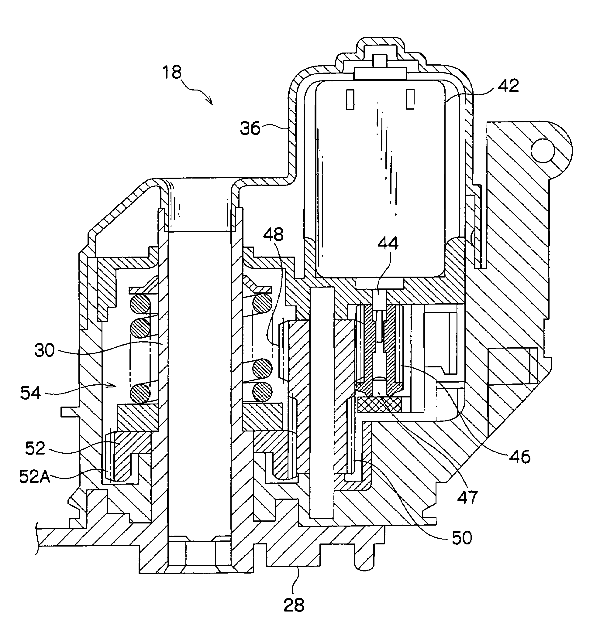
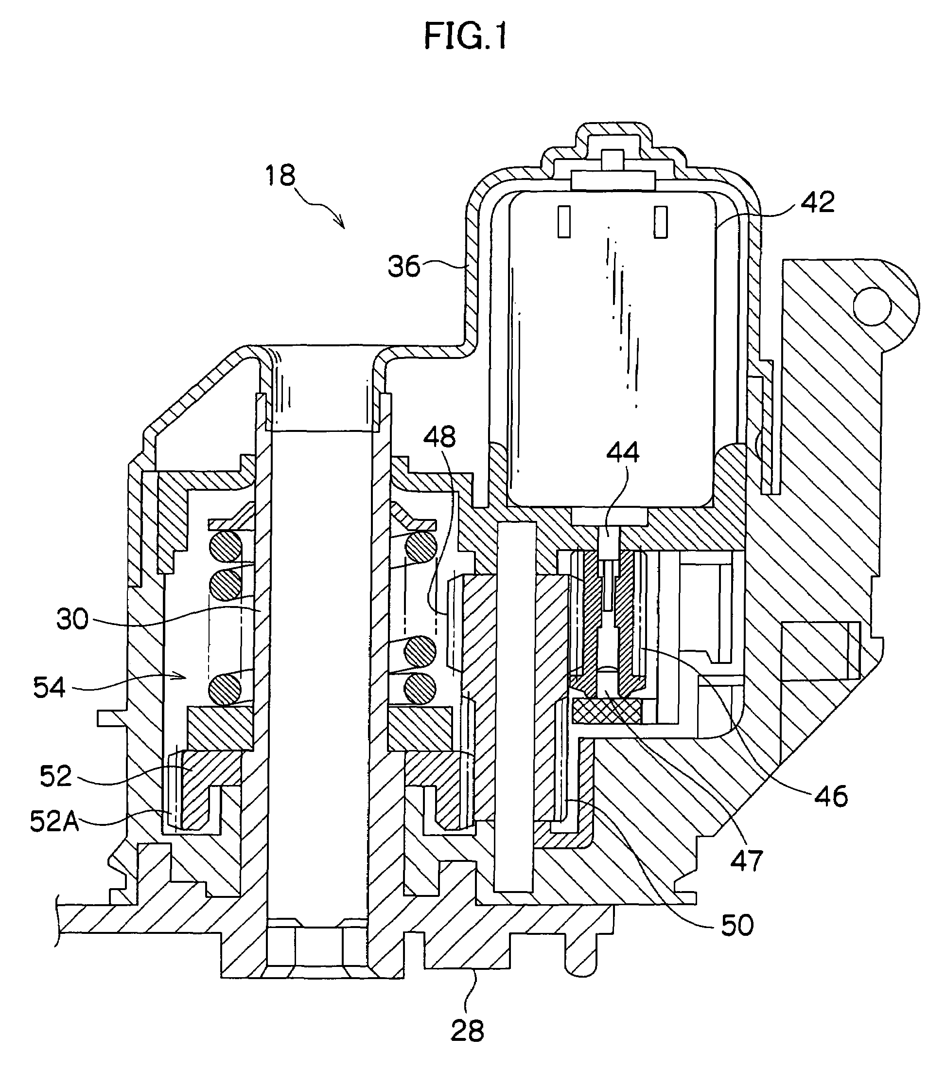
[0027]The vehicular outer mirror device 10 is formed as a door mirror device and includes a frame 12. A retaining member 14 is fixed to the frame 12, and a rearview mirror 16 is retained on the retaining member 14. The frame 12 is fixed to the retracting mechanism 18, which will be described in detail later. The retracting mechanism 18 is attached to a door mirror stay 20 that is fixed to a door (not shown) of a vehicle. Thus, the retracting mechanism 18 supports the mirror 16 via the frame 12 and the retaining member 14. The retracting mechanism 18 is a mechanism positioned in a deployed position, where it pivots the mirror 16 and is erect with respect to the door of the vehicle, and a stored position, where it is folded substantially along the door.

[0028]The frame 12, t...


PUM


Abstract

A retracting mechanism for storing or erecting a mirror includes, at a coupled portion of an output shaft of a drive motor and a worm gear, coupling retaining portions fitted together in a press-fitted state and rotational force transmitting portions opposing each other in a state where a predetermined gap is present between them. The coupling retaining portions are configured by a circular shaft portion and a circular fitting hole, and the rotational force transmitting portions are configured by a double D-cut portion and double D-protruding portions. The rotational force of the output shaft is transmitted by the rotational force transmitting portions, and the coupled state of the output shaft and the worm gear is retained on the same axial line and the slanting of the worm gear is prevented by the coupling retaining portions.

Description

CROSS-REFERENCE TO RELATED APPLICATION[0001]This application claims priority under 35 USC 119 from Japanese Patent Application No. 2004-261622, the disclosure of which is incorporated by reference herein.BACKGROUND OF THE INVENTION[0002]1. Field of the Invention[0003]The present invention relates to a retracting mechanism of a vehicular outer mirror device disposed in a vehicle.[0004]2. Description of the Related Art[0005]There is a vehicular door mirror device disposed with a retracting mechanism (e.g., see Japanese Patent Application Publication (JP-A) No. 2002-67805).[0006]This type of retracting mechanism includes a support shaft fixed to a vehicle body, and a case member is pivotably supported on the support shaft. A rearview mirror is coupled to the case member, and the case member is always pivoted integrally with the mirror.[0007]A gear plate formed as a helical gear is disposed on the support shaft inside the case member in a state where the rotation of the gear plate is pr...

Claims


Application Information

Patent Timeline
Patent Type & Authority Patents(United States)
IPC IPC(8): G02B5/08B60R1/06G02B7/182
CPCB60R1/074H02K7/1166F16H1/16Y10S248/90
Inventor YOSHIDA, SHIGEKITSUJIUCHI, YOSHIO
Owner KK TOKAI RIKA DENKI SEISAKUSHO
Why Eureka
Try Eureka