Laminate coil and brushless motor using same

a brushless motor and laminate coil technology, applied in the direction of magnetic circuit rotating parts, magnetic circuit shape/form/construction, magnetic bodies, etc., can solve the problems of uneven rotation and torque ripple, further miniaturization and thinning, and suffer from conventional coils. , to achieve the effect of excellent motor efficiency and high strength and productivity

Inactive Publication Date: 2007-11-06
HITACHI METALS LTD
View PDF8 Cites 53 Cited by
  • Summary
  • Abstract
  • Description
  • Claims
  • Application Information

AI Technical Summary

Benefits of technology

[0008]Accordingly, an object of the present invention is to provide a small, thin laminate coil having high strength and productivity and excellent motor efficiency free from uneven rotation and torque ripple, and a brushless motor comprising such a laminate coil.DISCLOSURE OF THE INVENTION

Problems solved by technology

However, such conventional coils suffer from the following problems.
In the coil disclosed by Japanese Utility Model Laid-Open No. 58-172345, because three-phase coils are obtained by forming toroidal pattern conductors for coil poles on thin insulating sheets by etching, plating, etc., and disposing them with displacement of a predetermined angle in a circumferential direction, (1) laminated coil layers should be bonded by uniform adhesive layers; (2) positional displacement between the bonded coil layers causes short-circuiting, etc. between the coil poles, resulting in the likelihood of uneven rotation and torque ripple; (3) sheets of polyimides, polyesters, etc. used as insulating sheets have limited mechanical strength, generally necessitating the insulating sheets to be disposed on the PCB or the yoke, thereby making further miniaturization and thinning difficult.
In addition, the existence of the external terminal electrodes enlarges the area of the laminate coil, resulting in a larger brushless motor.

Method used


Image

  • Laminate coil and brushless motor using same
  • Laminate coil and brushless motor using same
  • Laminate coil and brushless motor using same

Examples


first embodiment

[1] First Embodiment

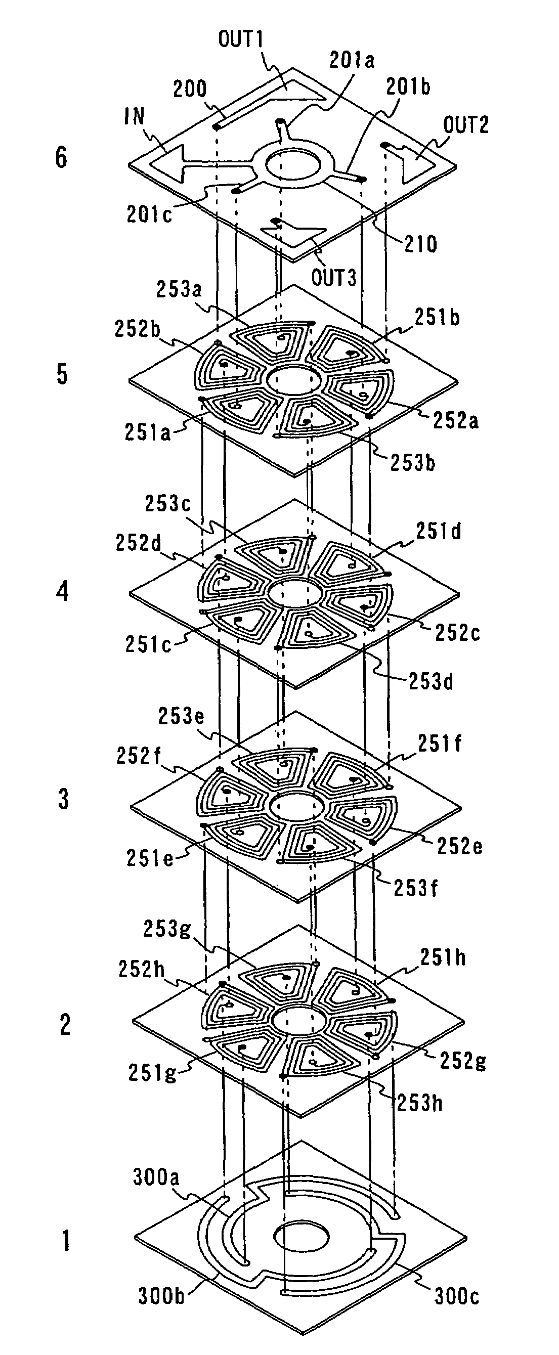
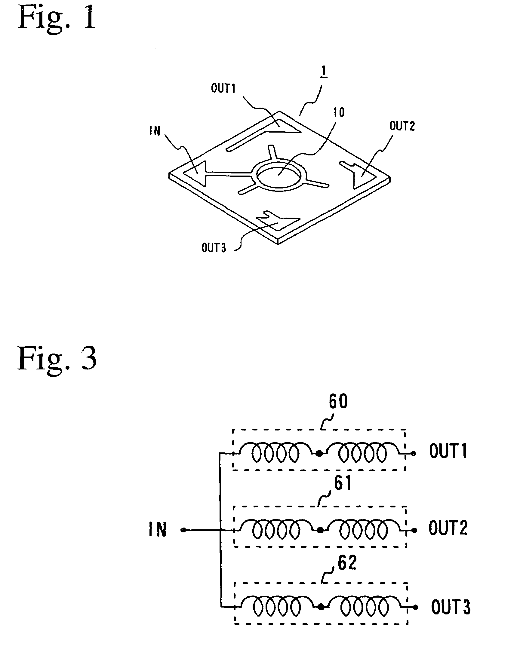
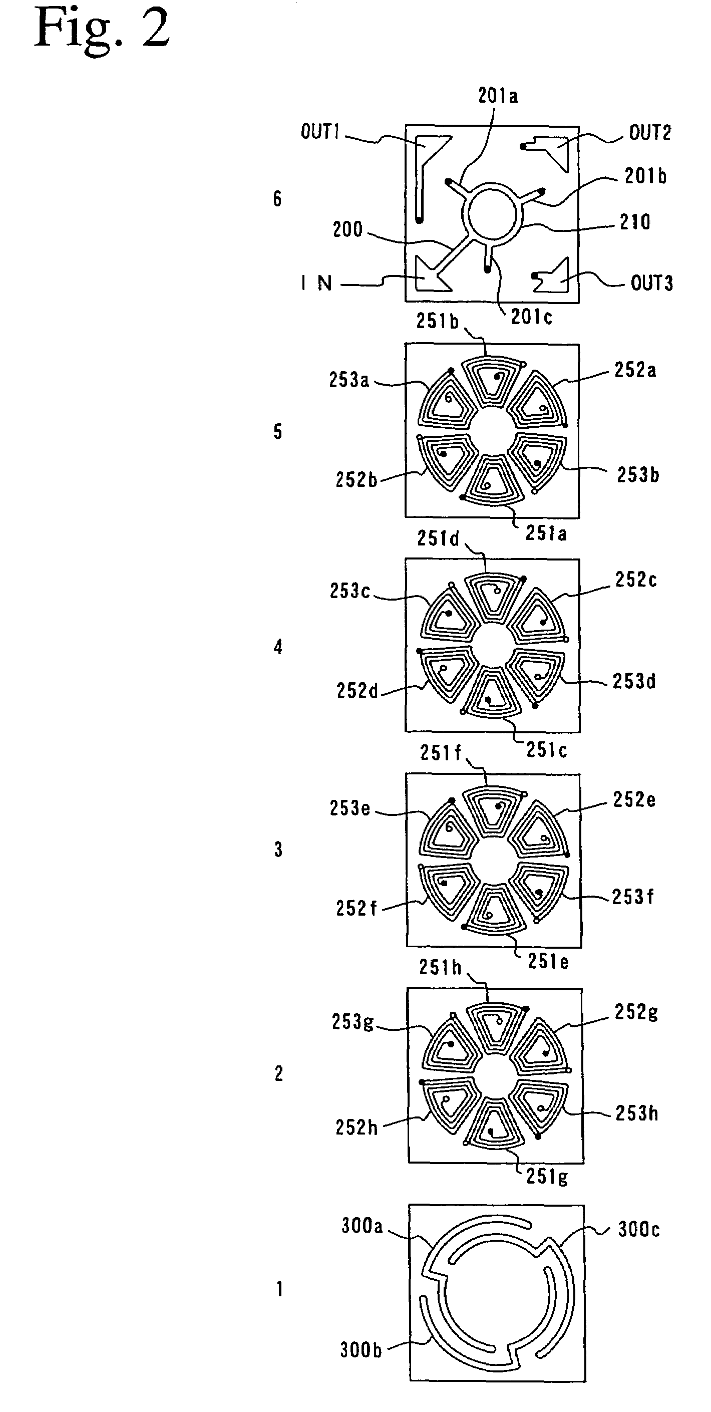
[0042]FIG. 1 is a perspective view showing the laminate coil 1 according to the first embodiment, and FIG. 2 is an exploded view showing its internal structure. This laminate coil 1, which integrally comprises pluralities of coil poles, may be formed by printing a conductive paste based on Ag, Cu, etc. on green sheets of a low-temperature co-fired ceramic (LTCC) having a thickness of 20 to 200 μm to form desired conductor patterns, and laminating and burning pluralities of green sheets having conductor patterns. The conductor patterns constituting the coil poles are preferably as wide as about 100 to 400 μm.

[0043]One example of methods for producing the laminate coil of the present invention will be explained in detail referring to FIGS. 9 and 10. First, a ceramic slurry comprising ceramic powder, a binder and a plasticizer is applied onto a carrier film made of polyethylene terephthalate, etc. in a uniform thickness by a known sheet-forming method such as a doct...

second embodiment

[2] Second Embodiment

[0074]FIG. 11 shows one example of a brushless motor constituted by the laminate coil of the present invention. The brushless motor shown in FIG. 11 comprises a first rotor 101a comprising an annular magnet 100 having N and S poles alternately as shown in FIG. 12, which is fixed to a yoke 105a, a rotation shaft 130 connected to a center of the first rotor 101a, a stator 125 comprising a laminate coil 1 facing the first rotor 101a via a predetermined magnetic gap, an electric signal controller (not shown) for periodically supplying driving electric current to coil poles 50 formed in the laminate coil 1, a PCB on which circuit patterns connected to the input and output terminals formed on the laminate coil 1 are formed, and a bearing 150 fixed to the stator 125 via a bushing 140 and supporting the rotation shaft 130 connected to the first rotor 101a such that the first rotor 101a smoothly rotates. This brushless motor uses three driving power sources.

[0075]The exp...

third embodiment

[3] Third Embodiment

[0081]FIG. 13 shows a further example of the brushless motor of the present invention. As shown in FIG. 12, this brushless motor comprises a first rotor 101a comprising an annular magnet 100 having N and S poles alternately, which is fixed to a yoke 105a, a second rotor 101b comprising annular magnet 100b, which is fixed to a yoke 105b such that the annular magnet 100b opposes the annular magnet 100a with their opposite poles facing each other, a rotation shaft 130 connected to a center hole of the first rotor 101a and a center hole of the second rotor 101b, a stator 125 facing the first and second rotors 101a, 101b via a predetermined gap and comprising a laminate coil 1 for applying an electromagnetic force of an opposite direction to the first and second rotors 101a, 101b, an electric signal controller for periodically supplying a driving electric current to coil poles 50 formed in the laminate coil 1, a PCB on which circuit patterns connected to input and out...


PUM

PropertyMeasurementUnit
open angleaaaaaaaaaa
thicknessaaaaaaaaaa
bending strengthaaaaaaaaaa

Abstract

A laminate coil for an integral n-phase motor (n is a natural number of 2 or more) having pluralities of coil poles formed by patterned conductor coils formed in a laminate constituted by pluralities of insulating layers, the laminate coil comprising input and output terminals formed on an outer surface of the laminate, a first connecting line connecting the input terminal to the coil poles, and second connecting lines series-connecting coil poles having the same polarity, the first and second connecting lines being formed by conductor patterns, and the coil poles being formed on pluralities of insulating layers sandwiched by the first and second connecting lines.

Description

CROSS REFERENCE TO RELATED APPLICATIONS[0001]This application is a 371 of PCT application serial No. PCT / JP03 / 10069, filed Aug. 7, 2003 and claims all rights of priority thereto, the PCT Application in turn claimed priority to Japanese Application Serial No. 2002-229522, Aug. 7, 2002.FIELD OF THE INVENTION[0002]The present invention relates to a small, thin, inexpensive brushless motor, and a laminate coil used therein.BACKGROUND OF THE INVENTION[0003]The miniaturization of electronic equipments results in stronger demand to provide smaller and thinner motors for use therein. As such a motor, Japanese Utility Model Laid-Open No. 58-172345, for instance, discloses a flat brushless motor comprising stator coils and a rotor having a permanent magnet opposing thereto, stator coils being constituted by laminating pluralities of sheet coils each formed by a spiral conductor pattern formed on an insulating substrate.[0004]In this flat brushless motor, as shown in FIGS. 14 to 16, motor magn...

Claims


Application Information

Patent Timeline
Patent Type & Authority Patents(United States)
IPC IPC(8): H02K17/00H02K3/26
CPCH02K3/26Y10T29/49071
Inventor ITOH, HIROYUKIHOURAI, TADAAKI
Owner HITACHI METALS LTD
Why Eureka
Try Eureka