Clipping with addition of vertices to existing primitives

Inactive Publication Date: 2007-11-06
NVIDIA CORP
View PDF3 Cites 52 Cited by
  • Summary
  • Abstract
  • Description
  • Claims
  • Application Information

AI Technical Summary

Benefits of technology

[0009]Embodiments of the present invention provide clipping techniques that introduce additional vertices into existing primitives without requiring creation of new primitives. For example, clipping a triangle to a plane may result in a clipped triangle with four vertices. The extra vertex can be hidden from the rasterizing and shading stages by suitable selection of edg

Problems solved by technology

Thus, clipping removes the invisible portions of primitives to support correct rendering, but at the cost of creating additional geometry, which increases the processing power required at subsequent stages.
Implementing clipless rasterizers,

Method used


Image

  • Clipping with addition of vertices to existing primitives
  • Clipping with addition of vertices to existing primitives
  • Clipping with addition of vertices to existing primitives

Examples


Embodiment Construction

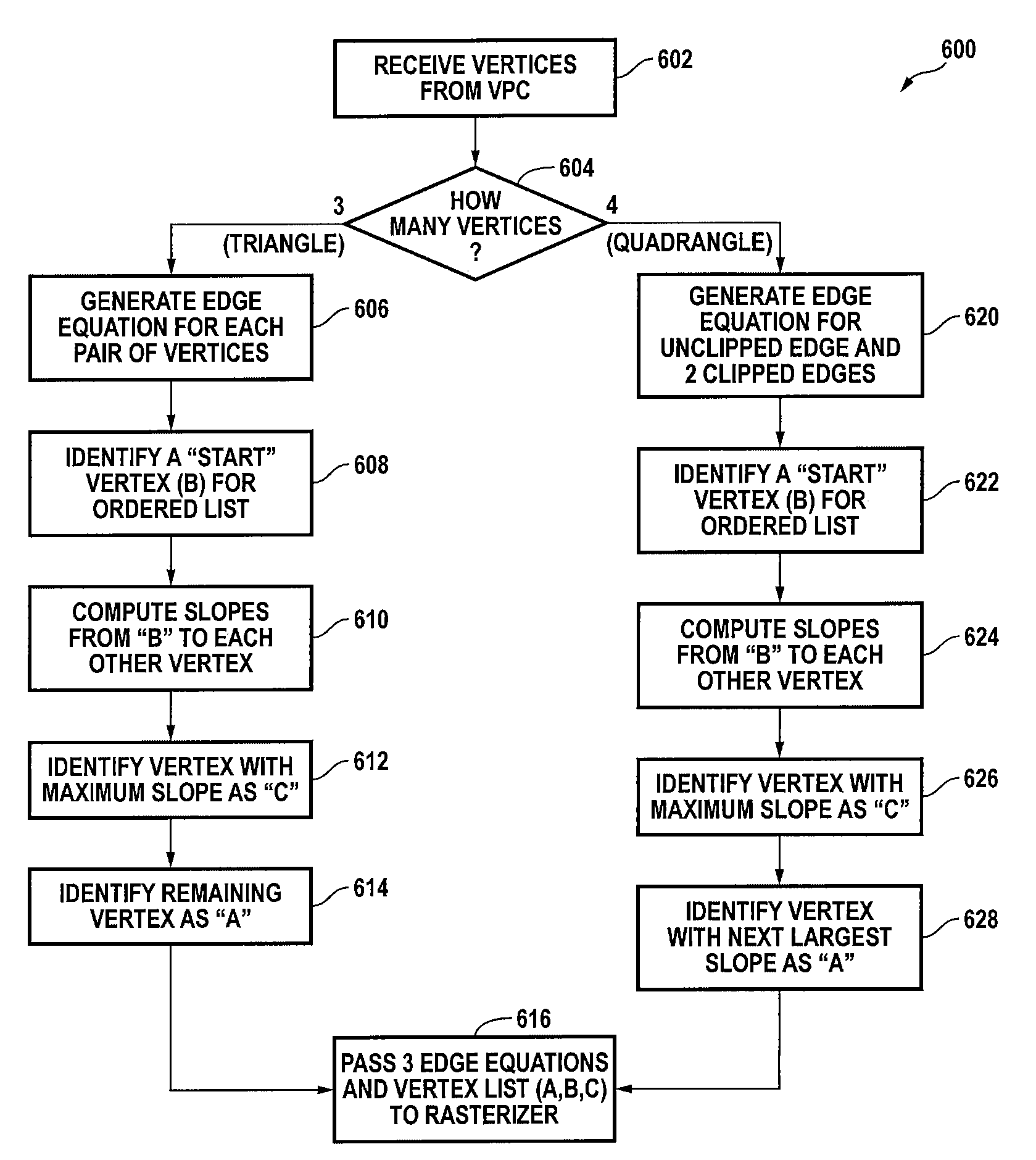
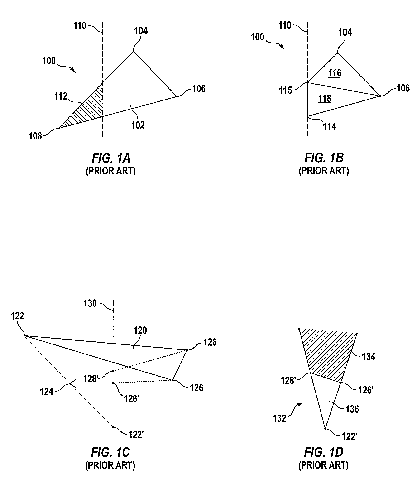
[0032]Embodiments of the present invention provide clipping techniques that introduce additional vertices into existing primitives without requiring creation of new primitives. For example, a triangle may be clipped to a near plane or other clipping surface defined such that points on one side of the surface are (at least potentially) visible and points on the other side are invisible. If the triangle has one invisible vertex (i.e., one vertex to the “invisible” side of the clipping surface), a four-vertex clipped triangle (referred to herein as a quadrangle) results. The extra vertex can be hidden from the rasterizing and shading stages by suitable selection of three edge equations for use in rasterization and three vertices for attribute computation during shading. For example, in the case of a quadrangle, three edges can be selected that will result in correct coverage determinations during rasterization (the fourth edge can be provided by the clipping surface itself), and any th...


PUM


Abstract

Clipping techniques introduce additional vertices into existing primitives without requiring creation of new primitives. For an input triangle with one vertex on the invisible side of a clipping surface, a quadrangle can be defined. The vertices of the quadrangle are the two internal vertices of the input triangle and two clipped vertices. For determining attribute values for pixel shading, three vertices of the quadrangle are selected, and a parameter value for an attribute equation is computed using the three selected vertices. For determining pixel coverage for the quadrangle, the three edges that do not correspond to the edge created by clipping are used.

Description

BACKGROUND OF THE INVENTION[0001]The present invention relates in general to computer-based rendering systems and in particular to rendering techniques for clipping geometry by addition of vertices to existing primitives.[0002]Three-dimensional (3D) rendering systems typically operate as pipelines. The pipeline receives geometry data in the form of primitives (usually lines and / or triangles) that represent various objects making up a scene. The primitives are generally defined by specifying vertices having spatial coordinates and other attributes, such as color components, texture coordinates, and the like. After a first pipeline stage transforms all of the objects to a common world coordinate system, the next pipeline stage transforms the objects to a viewing coordinate system, which is often expressed in 3D homogeneous (projective) coordinates (x, y, z, w), where all vectors (tx, ty, tz, tw) for t≠0 project to a single point (x / w, y / w, z / w) in 3D space. The viewing coordinate syst...

Claims


Application Information

Patent Timeline
IPC IPC(8): G06T15/40
CPCG06T15/30
Inventor WITTENBRINK, CRAIG M.MORETON, HENRY PACKARDVOORHIES, DOUGLAS A.MONTRYM, JOHN S.PARIKH, VIMAL S.
Owner NVIDIA CORP
Why Eureka
Try Eureka