Pin lift chuck assembly for warped substrates

a technology of substrate and chuck, which is applied in the direction of semiconductor/solid-state device manufacturing, basic electric elements, electric devices, etc., can solve the problems of distorted wafers that cannot be clamped on the chuck, can not be normally processed or handled by the inspection system, and can not achieve the effect of reducing the chuck, increasing the throughput of substrates, and saving time during normal wafer operation

Active Publication Date: 2007-11-06
KLA TENCOR TECH CORP
View PDF11 Cites 57 Cited by
  • Summary
  • Abstract
  • Description
  • Claims
  • Application Information

AI Technical Summary

Benefits of technology

[0008]Embodiments of the present invention facilitate effective chucking of warped substrates in spite of the effects of severe warpage through the use of specially designed lift pins that grab the backside of the substrate at three or more places and pull the substrate to conform to the chuck surface. Once the substrate has been pulled against the chuck surface by the lift pins, the chuck can hold the substrate in place with its normal chucking force.

Problems solved by technology

In semiconductor applications using metrology systems, one often encounters substrates (e.g., semiconductor wafers) that are non-planar to such a degree that they cannot normally be processed or handled by the inspection system.
Distorted wafers often cannot be clamped on a chuck to flatten them sufficiently for inspection in a metrology system.
Consequently, a significant loss of yield through the metrology system can result from the warping of the wafers.
This type of chuck is only effective for domed wafers up to approximately 400 μm of warpage and is not effective at all for bowled or asymmetric wafers.
Unfortunately, the degree of effectiveness is generally not known a priori and, consequently, effective chucking of warped wafers often requires expensive and complicated software and hardware.

Method used


Image

  • Pin lift chuck assembly for warped substrates
  • Pin lift chuck assembly for warped substrates
  • Pin lift chuck assembly for warped substrates

Examples


Embodiment Construction

[0017]Although the following detailed description contains many specific details for the purposes of illustration, anyone of ordinary skill in the art will appreciate that many variations and alterations to the following details are within the scope of the invention. Accordingly, the exemplary embodiments of the invention described below are set forth without any loss of generality to, and without imposing limitations upon, the claimed invention.

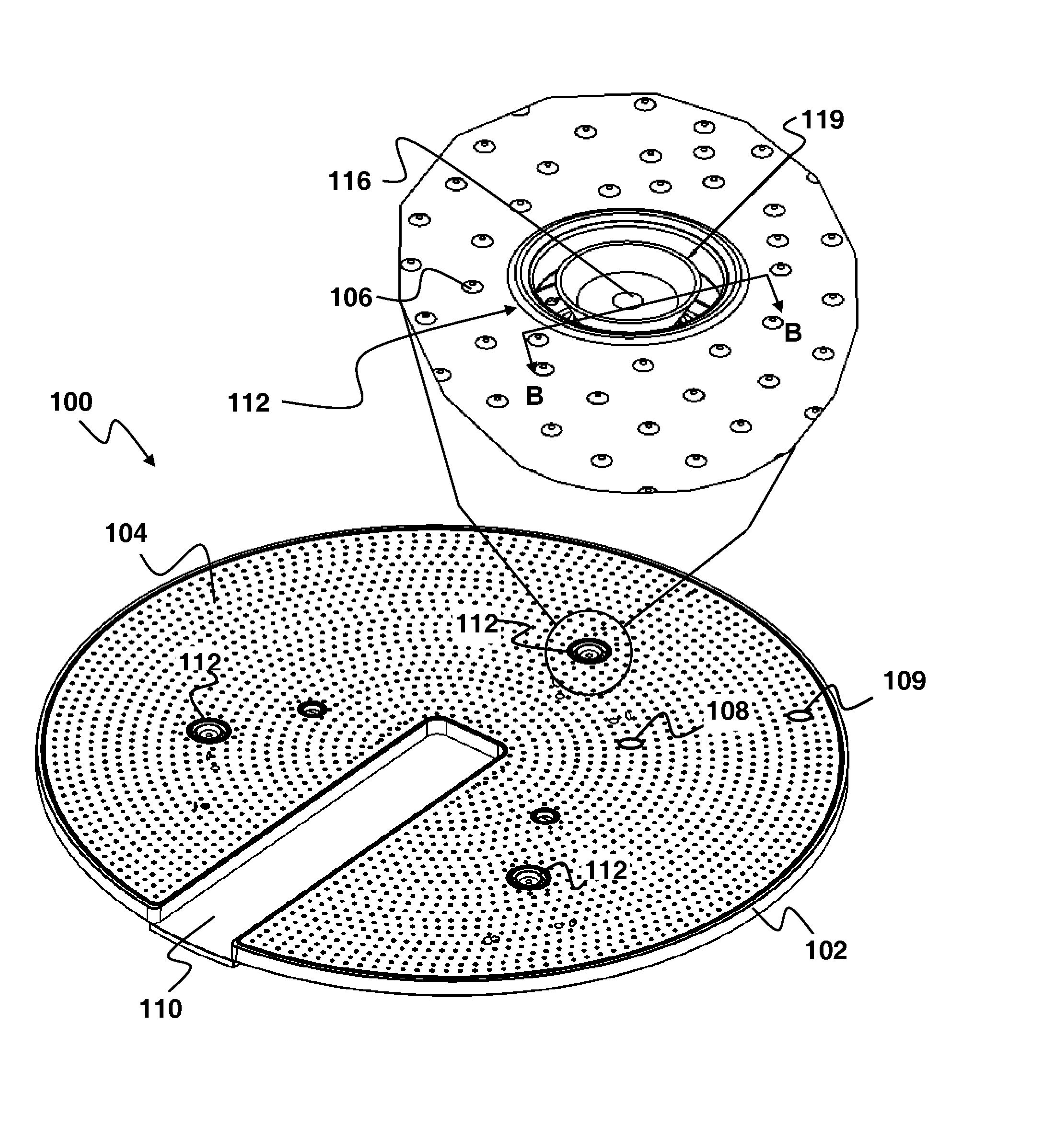
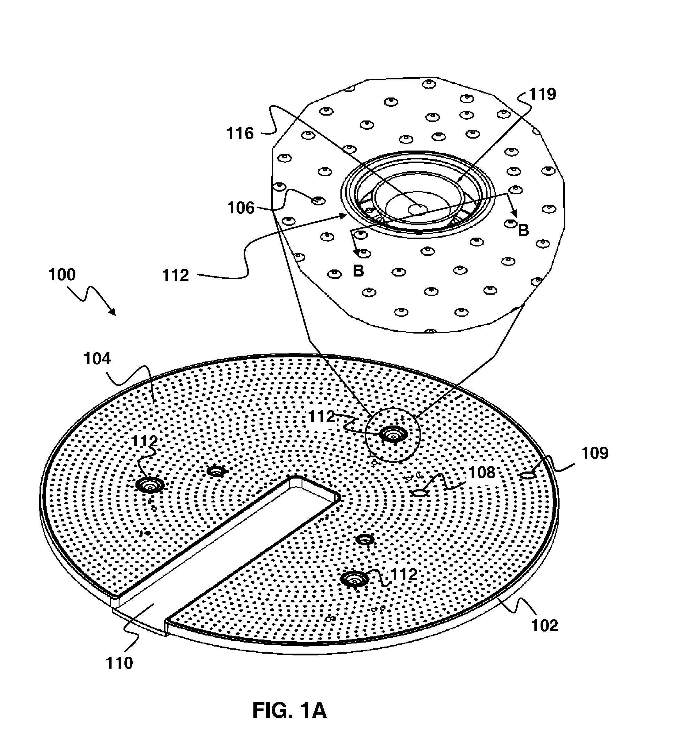
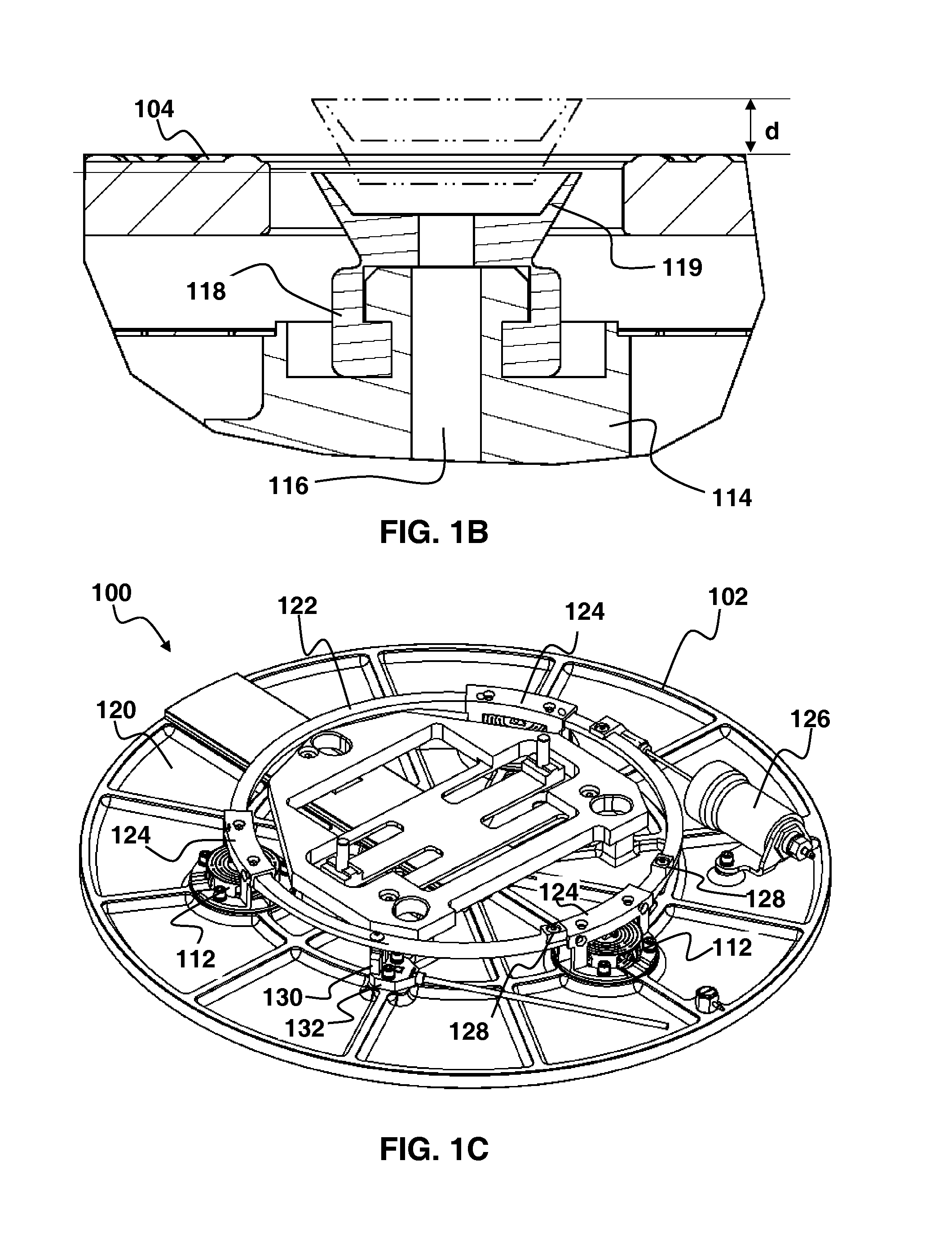
[0018]FIGS. 1A-1C depict an example of a vacuum chuck apparatus 100 according to an embodiment of the present invention. As shown in FIG. 1A, the vacuum chuck apparatus 100 generally includes a chuck body 102 having a substantially flat chucking surface 104. Rounded bumps 106 may be distributed across the chucking surface 104. It is common for chucks used in semiconductor processing to use such rounded bumps to reduce contact stress with the backside of a substrate such as a semiconductor wafer. The bumps 106 may be distributed to reduce or ...


PUM


Abstract

A vacuum chuck apparatus may include chuck plate having a substantially flat chucking surface, one or more lift pins, and a lifting mechanism. The lift pins are configured to clamp a substrate at three or more locations. The lifting mechanism lifts the heads of the pins above the level of the chucking surface subsequently lowers the pins to pull the substrate to substantially conform to the chucking surface. A warped substrate may be secured to the chuck surface by raising the lift pins above the surface of chuck, securing a backside of the substrate with the lift pins at three or more locations, and lowering the lift pins to draw the substrate against the surface of the chuck so that the substrate substantially conforms to the surface of the chuck.

Description

FIELD OF THE INVENTION[0001]This invention generally relates to substrate processing and more particularly to securing a substrate such that it conforms to a chuck surface.BACKGROUND OF THE INVENTION[0002]In semiconductor applications using metrology systems, one often encounters substrates (e.g., semiconductor wafers) that are non-planar to such a degree that they cannot normally be processed or handled by the inspection system. Such wafers may be warped as a result of upstream manufacturing processes (e.g., metal deposition) that change the planar flatness and cause these wafers to be bowl-shaped, dome-shaped, or asymmetrical (twisted). Metrology tools, such as bright field tools, often require substantially flat wafers. Wafers are typically clamped with a chuck to flatten them for metrology or processing. Distorted wafers often cannot be clamped on a chuck to flatten them sufficiently for inspection in a metrology system. Consequently, a significant loss of yield through the metr...

Claims


Application Information

Patent Timeline
Patent Type & Authority Patents(United States)
IPC IPC(8): H01L21/67
CPCH01L21/68714H01L21/6838
Inventor MURDOCH, STEVENBLOMGREN, TIMOTHY
Owner KLA TENCOR TECH CORP
Why Eureka
Try Eureka