DC/DC converter having transistor switches with flywheel diodes and program for controlling the transistor switches
a technology of transistor switches and transistor switches, which is applied in the direction of dc-dc conversion, power conversion systems, instruments, etc., can solve the problems of large size, high cost of dc/dc converters, non-uniform output voltage or power conversion efficiency drop, and achieve the effect of reducing the price of dc/dc converters
- Summary
- Abstract
- Description
- Claims
- Application Information
AI Technical Summary
Benefits of technology
Problems solved by technology
Method used
Image
Examples
first embodiment
[0106]A detailed description of the first embodiment of the present invention is provided as follows with reference to FIG. 1 to FIG. 9.
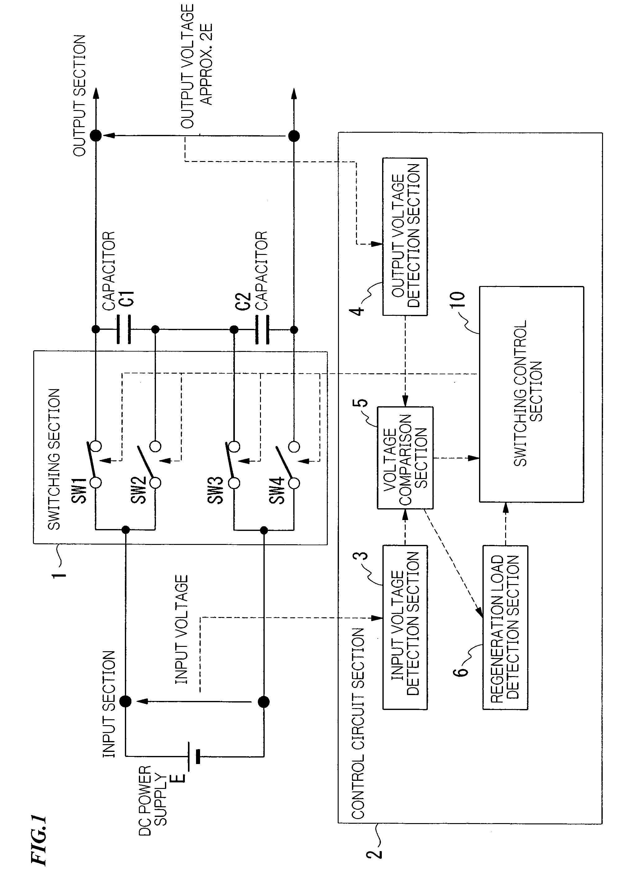
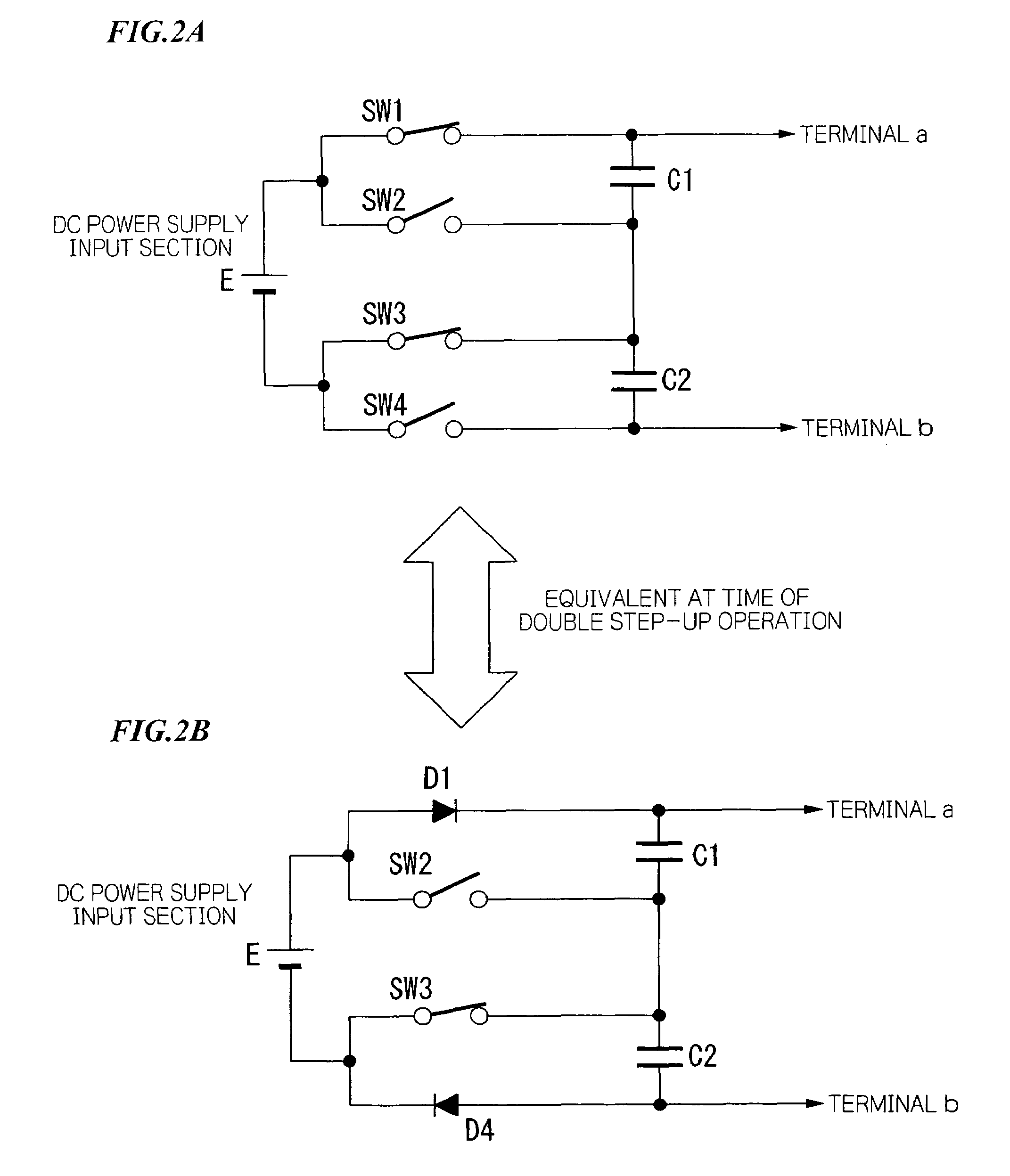
[0107]FIG. 1 is a diagram showing a fundamental construction example of a DC / DC converter according to the present embodiment. The DC / DC converter of the present embodiment has; a two times voltage step-up function (for example, voltage is stepped up to approximately two times the power supply voltage of the DC power supply input section), a one times voltage step-up function (for example the power supply voltage is output directly), and a voltage step-down function (power supply regeneration).
[0108]The DC / DC converter shown in FIG. 1 is provided with: a power supply E; a switching section 1 having a first switch SW1, a second switch SW2, a third switch SW3, and a fourth SW4; a first capacitor C1; a second capacitor C2; and an output section. The first capacitor C1 and the second capacitor C2 are connected in series. Film capacitors or the like are ...
first example
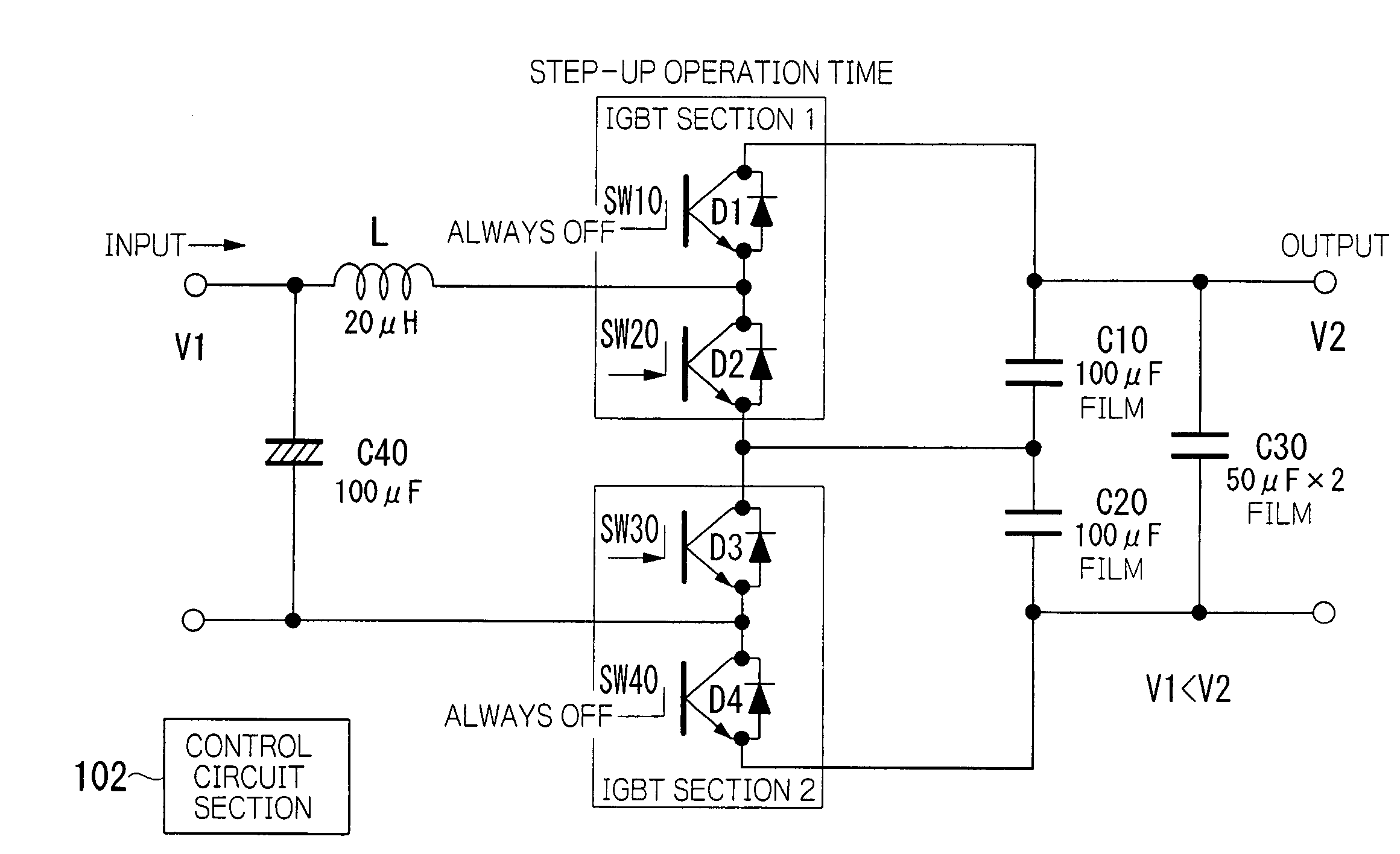
[0119]Next, an example of the DC / DC converter of the present invention is described. FIG. 4A is a diagram showing an example of the DC / DC converter according to the present invention. Moreover, this is a diagram for describing the operation at the time of a two times voltage step-up mode. FIG. 4B is a diagram showing the operation timing of the switches SW2 and SW3, and the waveform of the charging current to the capacitors C1 and C2.
[0120]The DC / DC converter shown in FIG. 4A has a power supply E, a smoothing capacitor (electrolytic capacitor) C4 on the input side, an IGBT section 1 and an IGBT section 2 comprising two (a pair of) IGBT devices, an inductor L and capacitors C1, C2 and C3. The capacitors C1, C2, and C3 are film capacitors in this example.
[0121]Comparing to the diagram for describing the operation of the two times voltage step-up shown in FIG. 3, the flying diode D1 of the IGBT device (SW1) on the upper side of the IGBT section 1 of FIG. 4A corresponds to the diode D1 ...
second embodiment
[0147]Hereinafter, the second embodiment of the present invention is described in detail with reference to FIG. 10 to FIG. 19.
[0148]FIG. 10 is a diagram showing a fundamental construction example of a DC / DC converter according to the present invention. The DC / DC converter of the present invention has a voltage step-up function (for example, voltage is stepped up to one to two times the power supply voltage of the DC power supply input section), and a power supply regeneration function.
[0149]The DC / DC converter shown in FIG. 10 is provided with: a power supply E of a DC power supply input section; an inductor L that accumulates magnetic energy; a switching section 1 having a plurality of switches SW10 to SW40; a first capacitor C10; a second capacitor C20; and an output section. The first capacitor C10 and the second capacitor C20 are connected in series.
[0150]FIG. 11A is a diagram showing a basic circuit that uses capacitors. The DC / DC converter of the present invention has a specia...
PUM
 Abstract
Description
Claims
Application Information
 - R&D
- Intellectual Property
- Life Sciences
- Materials
- Tech Scout
- Unparalleled Data Quality
- Higher Quality Content
- 60% Fewer Hallucinations
Browse by: Latest US Patents, China's latest patents, Technical Efficacy Thesaurus, Application Domain, Technology Topic, Popular Technical Reports.
© 2025 PatSnap. All rights reserved.Legal|Privacy policy|Modern Slavery Act Transparency Statement|Sitemap|About US| Contact US: help@patsnap.com


