Communication control method and communication control system

Inactive Publication Date: 2007-11-06
NTT DOCOMO INC
View PDF8 Cites 29 Cited by
  • Summary
  • Abstract
  • Description
  • Claims
  • Application Information

AI Technical Summary

Benefits of technology

[0011]The present invention has been made in view of the above problems, and thus has an object of providing a communication control method and a communication control system, which are capable of the effective use of a frequency band by detecting frequencies that may interfere with radio links being used, i.e., radio links being received, at other radio stations, and dynamically assigning a frequency band that prevents interference to a radio link when radio communication is conducted between the transmission side radio station and a reception side radio station in a radio network in which a plurality of the radio stations are deployed.

Problems solved by technology

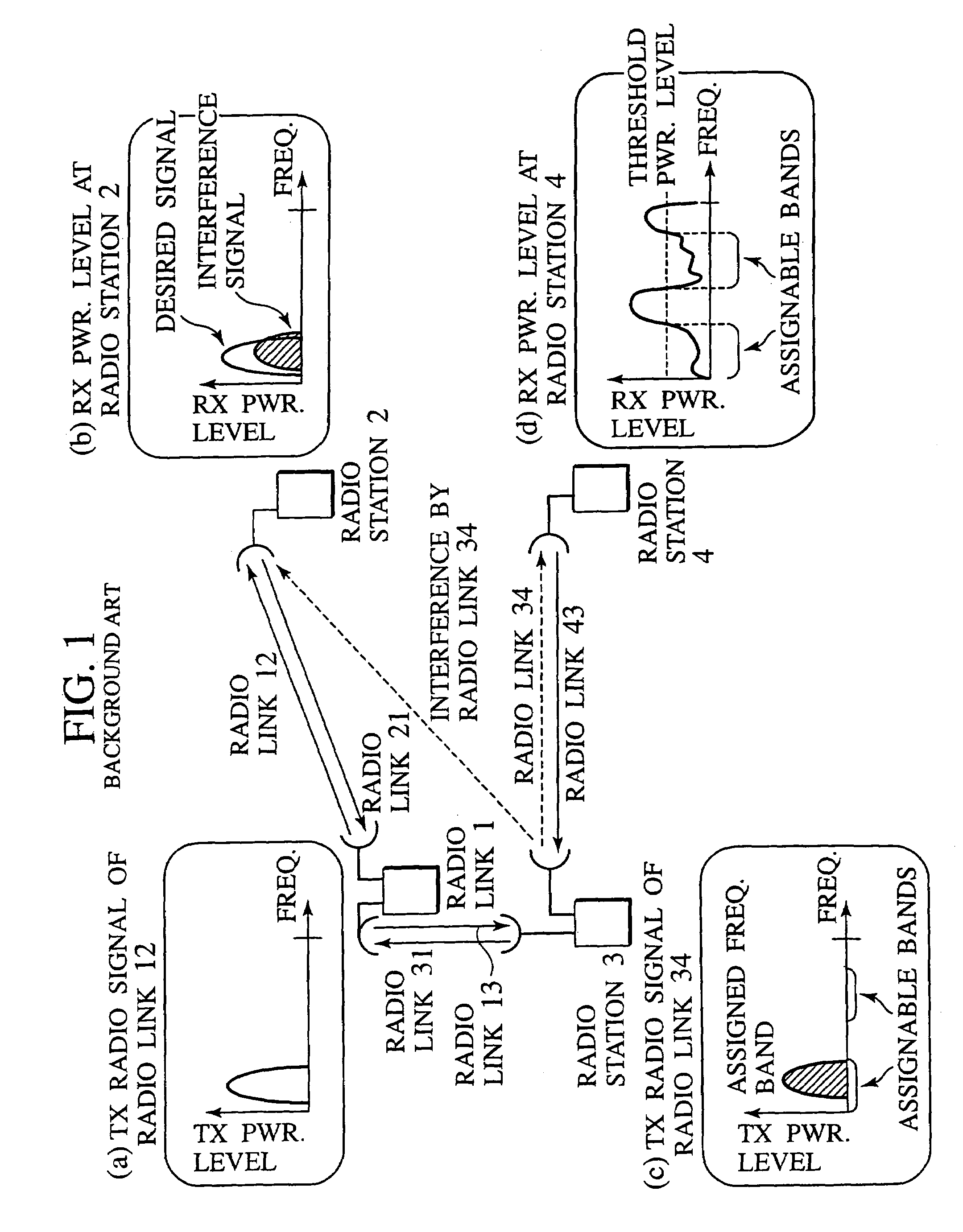
However, since interference that affects other radio links due to the assignment is not considered in the above conventional assignment method, interference that affects other radio links may occur due to the assignment of a frequency band to a radio link.
Otherwise, the reception power level of the interference may become greater at the other radio links and it may cause operational problems.
However, recognition of the frequency bands and interference levels being used by all the radio links is difficult in the conventional assignment method.

Method used


Image

  • Communication control method and communication control system
  • Communication control method and communication control system
  • Communication control method and communication control system

Examples


first embodiment

(Overview of Communication Control Method)

[0052]Hereinafter, a communication control system according to the first embodiment will be described. FIG. 2 is a schematic diagram showing the overall configuration of a communication control system according to this embodiment. In FIG. 2, 11 through 15 indicate radio links. Accordingly, radio stations 2 through 4 are interconnected by the radio links and the radio stations 2 through 4 transmit a notification signal that contains information regarding frequency band of radio links received at the radio station.

[0053]The radio station 2 measures the frequency and reception power level of the radio signal received at a reception antenna when a new frequency band is assigned to the radio link 11 and transmits the measured information to a transmission side radio station 1 as radio signal data. The transmission side radio station 1 receives the radio signal data and acquires the reception power level of the notification signals transmitted by ...

second embodiment

[0073]Hereinafter, the second embodiment of the present invention will be described. FIG. 7 is a schematic diagram showing an overview of a communication control system according to this embodiment. In FIG. 7, f1 and f2 indicate a frequency band on the traffic frequency band. The frequency bands are assigned to the radio links whereby bi-directional communication is being performed between the radio station 1 and the radio station 2.

[0074]As shown in FIG. 7, the radio station 1 and the radio station 2 transmit the notification signal that contains information regarding the frequency band of the received radio link, respectively. The radio station 3 can therefore recognize the frequency bands being used at the radio stations 1, 2, and 4 by receiving the notification signals. Thus, the radio station 3 can determine a frequency band, which will not interfere with the radio link between the radio station 1 and the radio station 2.

[0075]Especially, in this embodiment, each radio station ...

third embodiment

[0082]FIG. 9 is a schematic diagram showing a process of a communication control system according to the third embodiment. In FIG. 9, f1 through f5 show a frequency band on the traffic frequency band, and f1′ through f5′ show a frequency on the frequency band for control, which correlates with f1 through f5. Further, the frequency bands are assigned to radio links whereby bi-directional communications are being performed between the radio station 1 and the radio station 4, and between radio station 2 and the radio station 3, respectively.

[0083]The radio stations 1, 2, and 3 continually transmit the notification signal that correlates with the received frequency band with a certain interval as shown in FIGS. 9(a), (b) and (c). Each radio station may randomly determine transmission timing of the notification signal within a certain period of time. For instance, if a frequency band for a radio link from the radio station 4 to the radio station 5 is assigned, the radio station 5 measure...


PUM


Abstract

A reception side radio station has a notification signal generator 108 which transmits a notification signal for notifying information of a frequency of a radio link being used at the radio station, and a transmitter 111 which transmits information indicating a reception power level and its frequency as radio signal data. On the other hand, a transmission side radio station has a notification signal measurer 106 which measures a reception power level of the notification signal and detects the frequency notified by the signal, and a frequency band controller 109 which determines an assignable frequency band for a radio link between the transmission side radio station and the reception side radio station based on the radio signal data and the notification signal.

Description

CROSS REFERENCE TO RELATED APPLICATIONS[0001]This application is based upon and claims the benefit of priority from the prior Japanese Patent Application No. P2002-61119, filed on Mar. 6, 2002; the entire contents of which are incorporated herein by reference.BACKGROUND OF THE INVENTION[0002]1. Field of the Invention[0003]The present invention relates to a communication control method and a communication control system assigning a usable frequency band when conducting radio communication between a transmission side base station and a reception side base station in a radio communication network in which a plurality of radio stations are deployed.[0004]2. Description of the Related Art[0005]Conventionally, a usable frequency band is assigned to a radio link when conducting communication between a transmission side base station and a reception side base station on a radio communication network in which a plurality of radio stations are deployed. FIG. 1 shows a conventional assignment m...

Claims


Application Information

Patent Timeline
IPC IPC(8): H04B1/10H04B15/00H04W16/10H04L12/28H04W72/08
CPCH04W72/08H04W72/0453H04W72/54
Inventor YAMAGUCHI, KOICHIROABURAKAWA, YUJINAKAYAMA, YUJIOTSU, TORU
Owner NTT DOCOMO INC
Why Eureka
Try Eureka