Bearing device

a bearing and bearing technology, applied in the direction of machines/engines, liquid fuel engines, positive displacement liquid engines, etc., can solve the problems of increased cost, troublesome installation, and inability to meet the needs of the customer,

Inactive Publication Date: 2007-11-13
JTEKT CORP
View PDF18 Cites 35 Cited by
  • Summary
  • Abstract
  • Description
  • Claims
  • Application Information

AI Technical Summary

Benefits of technology

[0012]As described above, the lubricant supply unit body is additionally disposed in the bearing device, and hence the lubricant supply unit can be easily mounted. In addition, the bearing device can be made more compact. The lubricant supply unit body supplies lubricant to the bearing device as necessary. Consequently, there is not any waste such as that lubricant is supplied in an unnecessary occasion. Thus, it is possible to contribute to the long-term stabilization of the rolling property.
[0014]In the case where the driving portion is an electric generator having a power generating capacity according to the rotational speed of the bearing, the amount of lubricant discharged by the pump can be controlled in accordance with the power generating capacity of the electric generator. When the amount of lubricant discharged by the pump is controlled in accordance with the rotational speed of the bearing device as described above, an appropriate amount of lubricant can be supplied, and excess and deficient states can be eliminated.
[0018]In the above-mentioned means, the fuel cell can drive a functioning element (pump) for a longer time as compared with a primary battery or a secondary battery having the same size, so that automatic operation for a long term can be realized.
[0021]In this configuration, since the unit body has a ring-like shape and is disposed coaxially with the raceway members, the entire bearing to which the unit body is attached can be made to have the same shape as the ring-like raceway member. Thus, the bearing device can be incorporated in the same space as that for a usual bearing device, and the degree of freedom in apparatus design is enhanced.
[0032]According to the means, the lubrication condition of the interior of the bearing can be sensed, and hence the lubrication can be appropriately controlled while monitoring the condition of lubricant.

Problems solved by technology

The prior art lubricant supply unit is required to be disposed as a unit separate from the rolling bearing, and hence its installation is troublesome.
Therefore, the size of the rolling bearing is inevitably made larger, and it is necessary to ensure a pump mounting area in the outer ring of the rolling bearing.
Accordingly, there is a fear that the cost is increased.
Therefore, downsizing thereof is limited.
In the configuration, however, a magnet and a coil for the generator must be mounted, and hence there are severe restrictions on the space.
Thus, it is difficult for the current configuration to be applied to a bearing of a smaller size.

Method used


Image

  • Bearing device
  • Bearing device
  • Bearing device

Examples


first embodiment

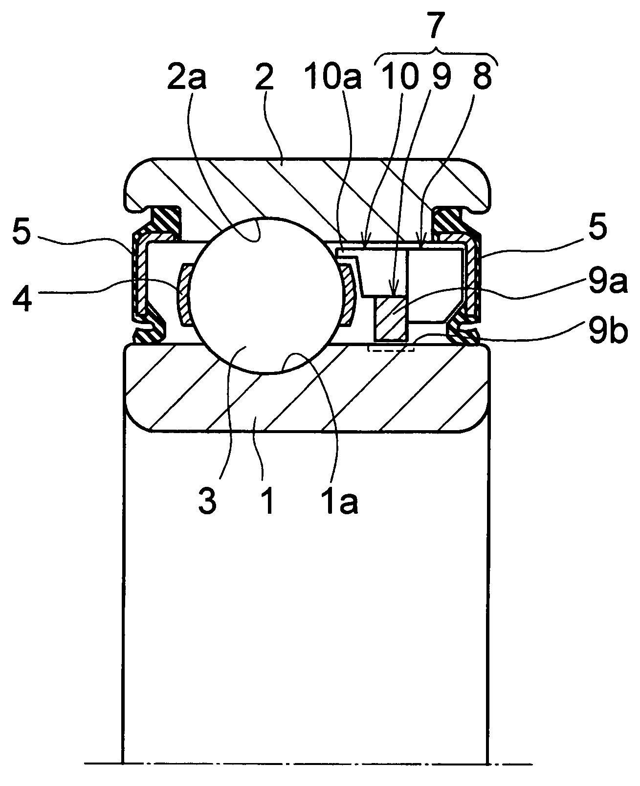
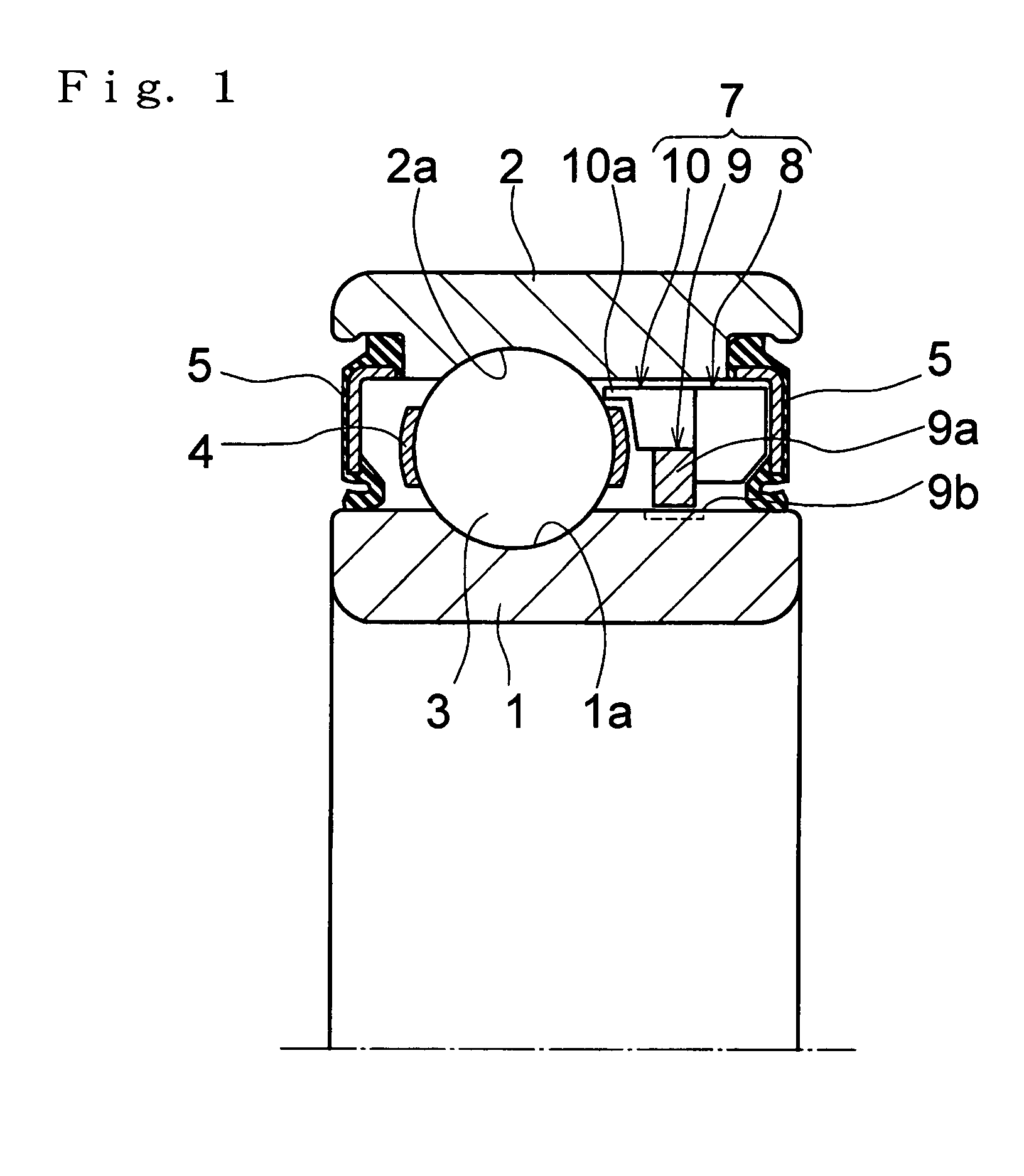
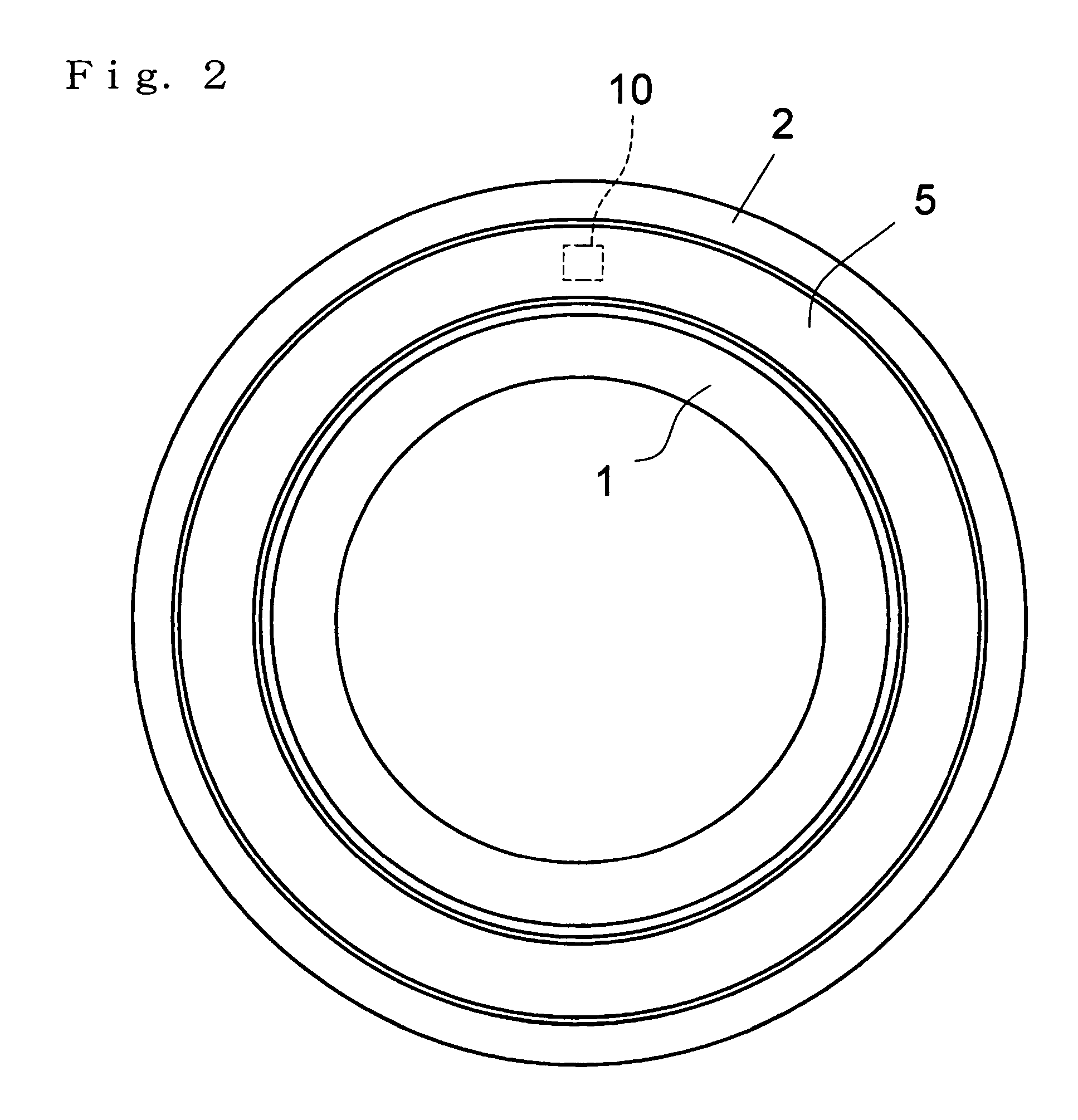
[0048]Hereinafter, specific embodiments of the invention will be described. FIGS. 1 to 3 show the invention. In the figures, 1 denotes an inner ring, 2 denotes an outer ring, 3 denotes a plurality of balls serving as rolling elements, 4 denotes a cage, and 5, 5 denote seal rings.

[0049]The illustrated bearing device is a bearing which is a rolling bearing, and which is called a deep groove ball bearing. In the bearing device, the plurality of balls 3 serving as a plurality of rolling elements are interposed between raceway grooves 1a, 2a disposed in the inner and outer rings 1, 2 serving as a plurality of raceway members, and the plurality of balls 3 are held by the cage ring 4 which is called a pressed cage. In the bearing device, the outer ring 2 is a stationary race ring, and the inner ring 1 is a rotating race ring. The seal rings 5, 5 are attached to both shoulder portions of an inner circumferential face of the outer ring 2 serving as the stationary race ring, and are in contac...

second embodiment

[0061]Next, FIGS. 4 to 8 show the invention.

[0062]FIG. 4 is a section view showing the configuration of the second embodiment of the bearing device of the invention, looking in a direction perpendicular to the axial direction (a view along the line X-X looking in the direction of the arrows in FIG. 5 which will be described below). FIG. 5 is a section view taken along the line A-A looking in the direction of the arrows in FIG. 4, FIG. 6 is a section view taken along the line B-B looking in the direction of the arrows in FIG. 4, and FIG. 7 is a section view taken along the line C-C looking in the direction of the arrows in FIG. 4.

[0063]The bearing device is configured by: an inner ring 1 and an outer ring 2 which serve as ring-like members (raceway members); rolling elements (balls) 3 which are disposed at regular intervals in a circumferential direction of an annular space P between opposed faces of the outer and inner rings; a cage 4 which holds the rolling elements 3; seal rings 5...

third embodiment

[0079]FIG. 9 is a view showing the bearing device of the invention, and showing the configuration of the bearing device in which a fuel cell is used as one kind of the battery 6. In this case, for example, a methanol tank 13 for supplying hydrogen to the fuel cell 6 is disposed in the unit body 7.

[0080]In the three embodiments described above, the bearing device of the invention is a so-called bearing of the deep groove type configured by the inner ring 1, the outer ring 2, and the rolling elements (balls) 3 held by the cage 4. The invention is not restricted to this, and may be applied to all types of bearings such as a bearing of the angular type, a cylindrical roller bearing, and a conical rolling bearing.

[0081]As a fuel source for the fuel cell 6 of the unit body 7, methanol in the tank 13 is used. It is a matter of course that hydrogen can be obtained by reforming a natural gas or a gasoline, in place of methanol. In this case, a corresponding fuel tank is used. Moreover, needl...


PUM


Abstract

A bearing device mountable on a smaller bearing and allowing to be automatically lubricated for a long period, comprising an inner ring and an outer ring rotated relative to each other, cages and rolling elements held by the cages which are disposed in an annular space between the inner and outer rings, a seal ring disposed on both sides of the inner and outer rings, and a unit body formed of a battery, a tank for storing lubricant, and a pump sucking and discharging the lubricant from the tank which is disposed between the outer ring and the inner ring detachably from the seal ring, wherein the lubricant is discharged from the pump into the annular space in which the rolling elements are disposed and the discharged amount of the lubricant from the pump is controlled by a sensor and a control circuit, and the unit body is formed detachable, whereby a lubrication unit installed in the bearing can be made compact and slim.

Description

TECHNICAL FIELD[0001]The present invention relates to a bearing device, and more particularly to a bearing device in which a lubricant storing tank, a pump, and a driving portion for the pump are disposed as a unit.BACKGROUND ART[0002]Conventionally, a lubricant supply unit (lubricating device) which supplies a very small amount of lubricant to a rolling bearing has been proposed (see Japanese Patent Publication (Kokai) No. 2002-130593). In the lubricant supply unit, a tank is disposed distantly from a position where the rolling bearing is disposed, a nozzle is disposed so as to face a space between an inner ring and an outer ring of the rolling bearing, and the tank and the nozzle are connected together via a lubricant supply path.[0003]The prior art lubricant supply unit is required to be disposed as a unit separate from the rolling bearing, and hence its installation is troublesome. By contrast, a configuration in which a lubrication pump for discharging lubricant is disposed ins...

Claims


Application Information

Patent Timeline
Patent Type & Authority Patents(United States)
IPC IPC(8): F16C33/66F04B23/02F04B43/04F04B53/18F16C33/10F16N7/38
CPCF04B23/025F04B43/04F04B43/046F04B53/18F16C33/6655F16C33/6674F16N7/38F16C33/6651F16C2240/02F16C33/664F16C41/004F16C19/06
Inventor UENO, HIROSHIOHTSUKI, MASAAKIFUKUDA, SHINJISAKAMOTO, KENJIEGUCHI, SYOUJI
Owner JTEKT CORP
Why Eureka
Try Eureka