Method of branching power around an obstacle

a technology of branching power and obstacles, applied in the direction of coupling device connections, coupling device details, connection contact material, etc., can solve problems such as forming electrical connections between adjacent panels

Inactive Publication Date: 2007-11-13
GROUP DEKKO
View PDF4 Cites 25 Cited by
  • Summary
  • Abstract
  • Description
  • Claims
  • Application Information

AI Technical Summary

Benefits of technology

[0011]An advantage of the present invention is that power is routed around the outside of an obstruction while still providing all the branching capability of the traditional branching methods.
[0012]Another advantage is that all conventional circuitry options may be implemented in thin panels.
[0013]A further advantage of the inven

Problems solved by technology

One recurrent problem in electrified office partitions is forming an electrical connection between adjacent panels.
The problem has been largely resolved for panels of sufficient width to accommodate jumpers or connections passing around corners, but with more narrow width panels, support post

Method used


Image

  • Method of branching power around an obstacle
  • Method of branching power around an obstacle
  • Method of branching power around an obstacle

Examples


Embodiment Construction

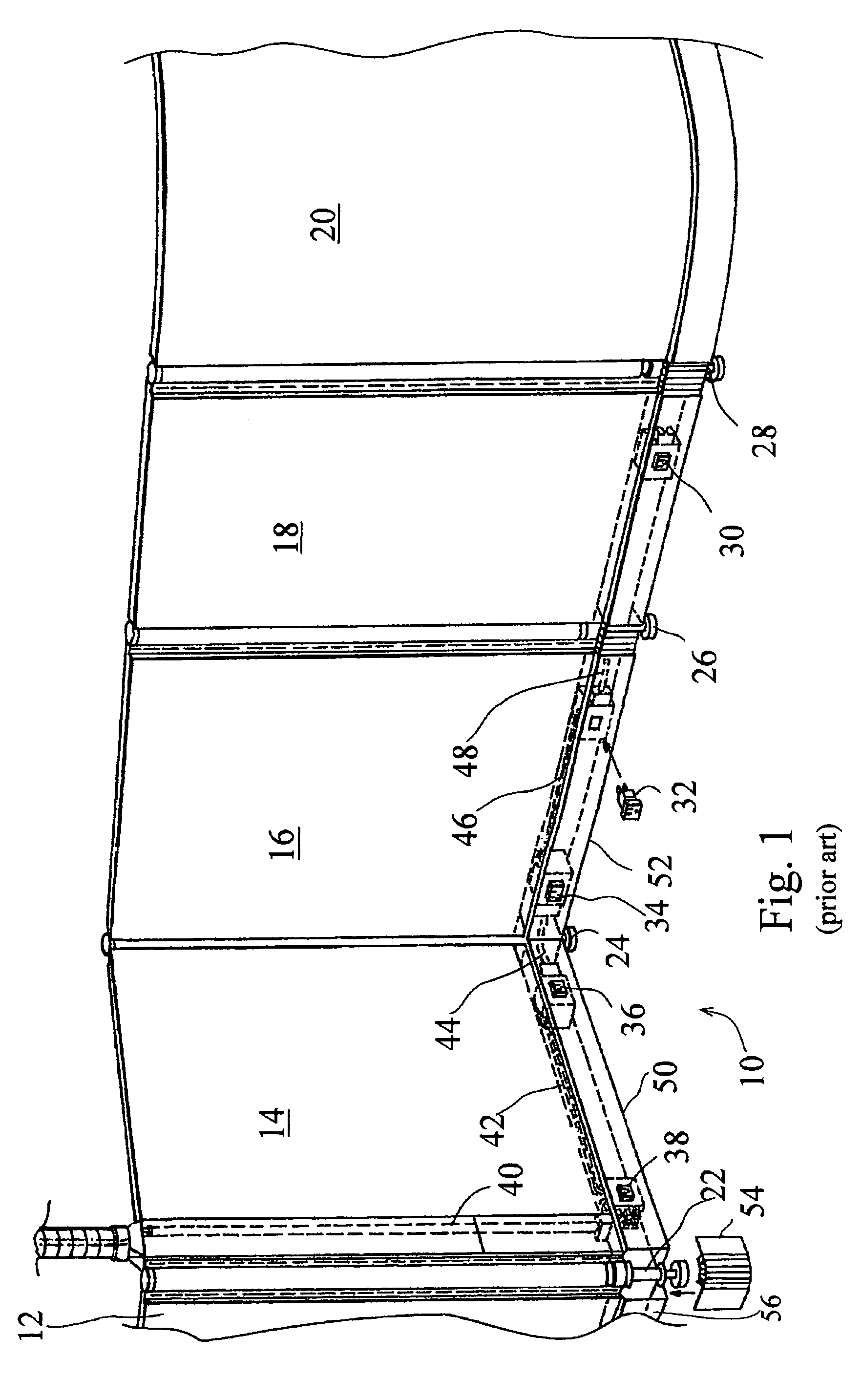
[0040]Referring now to the drawings, and more particularly to FIG. 1, there is shown an illustrative office or workspace divider panel or partition system 10 which includes a series of wall sections 12, 14, 16, 18 and 20 which rest on posts or supports 22, 24, 26 and 28. Individual wall panels are electrified, that is, provided with electrical outlets or receptacles such as 30, 32, 34, 36 and 38 which are provided with electrical energy from source above by a power downfeed line 40. The individual outlets are electrically interconnected by jumpers such as 42, 44 and 46. Jumper 48 is shown as providing power upwardly from outlet 32 to a utilization device located overhead or higher on a wall panel. Jumper 48 could extend to other electrical components such as receptacle 30 as desired. The electrical outlets and interconnecting jumpers are disposed in panel raceways such as 50, 52 and 56 which interconnect to form a channel which extends along the bottom edges of the several panels. N...


PUM


Abstract

A modular furniture power distribution system has a plurality of multiconductor electrical cables (42, 44, 46, 48, 62), each having an electrical connector (98, 100, 102) at a first and second ends. There are at least two upstanding partition panels (58), each having an elongated generally horizontally extending channel or raceway (60) for receiving a corresponding electrical cable, and a stanchion or leg (68, 70, 72, 74) for supporting juxtaposed partition panel ends. The support stanchion forms an obstacle precluding direct communication between adjacent partition channels because it provides inadequate clearance to accommodate an electrical coupling between the electrical connector in one channel and the corresponding electrical connector in the other panel. A collar (80) at least partially encircles the leg or other support structure and forms an electrical coupling for circumventing the obstacle and electrically coupling a connector of the cable in one channel with a corresponding connector of the cable in the other channel. A pair of electrical connectors (84, 88) at opposite ends of the collar are adapted to mate with corresponding cable connectors (98, 100) and the mating cable connector and collar connector pairs engage and disengage by relative motion in the direction (90) of channel elongation.

Description

CROSS REFERENCE TO RELATED APPLICATIONS[0001]This is a non-provisional application based upon U.S. provisional patent application Ser. No. 60 / 653,807, entitled “METHOD OF BRANCHING POWER AROUND AN OBSTACLE”, filed Feb. 17, 2005.BACKGROUND OF THE INVENTION[0002]1. Field of the Invention[0003]The present invention relates to power distribution systems, and, more particularly, to power distribution systems of the type utilized with movable partitions or similar modular furniture having raceways for distributing electrical energy.[0004]2. Description of the Related Art[0005]Modular furniture power distribution systems typically may be configured by the user without the need for tools or the services of a professional electrician. Electrical distribution systems for electrified office partitions and similar modular furnishings with power and / or communications wiring running in raceways along the top, beltline or bottom of the partitions have been known for a number of years.[0006]One rec...

Claims


Application Information

Patent Timeline
IPC IPC(8): H01R4/60
CPCH01R25/162H01R13/514
Inventor LAUKHUF, GREGG
Owner GROUP DEKKO
Why Eureka
Try Eureka