Fixture with integral stops

a technology of fixing and stops, applied in the field of fixings, can solve the problems of significant disadvantages of adhesive backed fixtures described in the above-identified patents, constructions which will not allow the use of clamps to secure attachments, and the use of suction cups is limited to being used on smooth substrates. the effect of quick and easy removal of the attachment and the substra

Active Publication Date: 2007-11-13
NMC GROUP
View PDF2 Cites 12 Cited by
  • Summary
  • Abstract
  • Description
  • Claims
  • Application Information

AI Technical Summary

Benefits of technology

[0012]Finally, the fixture of the present invention includes a stop which ensures that the inner retainer is not forced beyond the predetermined second position when the inner retainer is moved from the first position to the second position. In a first embodiment, the stop projects radially outward from the inner retainer's proximal extremity. The stop is sized and positioned so as to engage the outer support member's proximal extremity when the inner retainer is moved into the second position. Upon the stop engaging the outer support member's proximal extremity, the inner retainer is restricted from further telescopic movement in the distal direction.
[0013]In use, an attachment in the form of a fastener or patch or the like is releasably attached to the distal extremity of the fixture's inner retainer. The attachment may be preconstructed to include an adhesive. Alternatively, a suitable quantity of adhesive material such as an epoxy resin, is applied to the underside of the attachment or directly to the substrate. The fixture is then temporarily secured to the substrate at a selected location by forcing the outer support member's adhesive backed distal extremity upon the substrate. When the fixture is first secured to the substrate, the inner retainer is initially located in the first position so that the attachment is not in bearing engagement with the substrate. However, the inner retainer is then manually forced from the first position to the second position by pushing on the inner retainer's proximal extremity until the inner retainer's stop engages the outer support member. Once the stop has engaged the outer support member, the fixture exerts a predetermined force upon the attachment against the substrate. Once the attachment's adhesive has properly cured, the fixture can be quickly and easily removed from the attachment and substrate. One merely lifts the fixture from the substrate to break the temporary adherence between the outer support member and substrate, leaving the attachment permanently affixed to the substrate.

Problems solved by technology

Unfortunately, many substrates have constructions which will not allow the use of a clamp to secure an attachment in place.
However, suction cup devices are limited to being used on substrates having smooth surfaces.
Unfortunately, the adhesive backed fixtures described in the above-identified patents suffer from a significant disadvantage.
In particular, persons applying such fixtures and their corresponding attachments to a substrate will often unintentionally place too much pressure upon the inner retainer.
This excessive force causes adhesive material between the attachment and substrate to squeeze out from between the respective parts resulting in a weakened joint between the attachment and substrate when the adhesive cures.
Unfortunately, the prior art fixtures do not include a means for preventing excessive force upon the inner retainer being transmitted to the attachment.
Unfortunately, when persons place force upon the inner retainer, often they will place excessive force on the retainer causing the adhesive 4 to seep from between the fastener and substrate resulting in a weakened bond.
Fixture devices including spokes also have not been devised to include a structure for preventing excessive seepage of the adhesive caused by excessive force upon the inner retainer.

Method used


Image

  • Fixture with integral stops
  • Fixture with integral stops
  • Fixture with integral stops

Examples


Embodiment Construction

[0032]While the present invention is susceptible of embodiment in various forms, as shown in the drawings, hereinafter will be described the presently preferred embodiments of the invention with the understanding that the present disclosure is to be considered as an exemplification of the invention, and it is not intended to limit the invention to the specific embodiments illustrated.

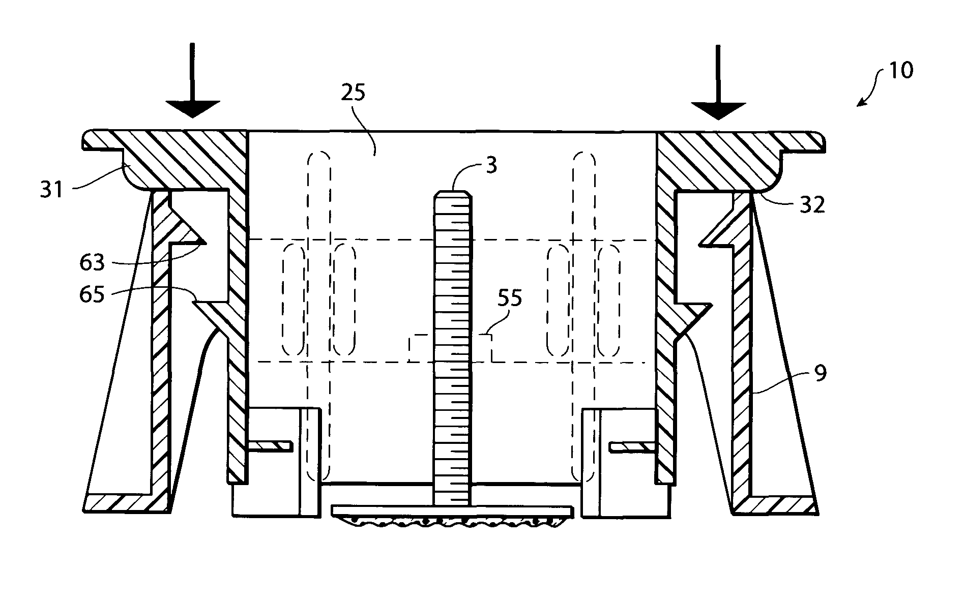
[0033]As shown in FIGS. 7-15, I have provided an improved fixture 1 for affixing attachments 3 to a substrate 6. The fixture 1 includes two primary components, an outer support member 9 and an inner retainer 25.

[0034]The outer support member 9 includes adhesive pads 16 at the outer support member's distal extremities 15 for temporarily affixing to a substrate 6. The outer support member 9 may be oval, circular or rectangular in construction. However, as shown in the figures, a preferred support member presents a substantially rectangular footprint, and includes a pair of side walls 11 and end walls 13. ...


PUM

PropertyMeasurementUnit
flexibleaaaaaaaaaa
adhesiveaaaaaaaaaa
pressureaaaaaaaaaa

Abstract

An improved fixture is provided for securely mounting attachments to an underlying substrate. The fixture includes an outer support member, an inner retainer, a biasing means for biasing the inner retainer relative to the outer support member, and stops for controlling movement between the retainer and support member. The outer support member includes a central bore for receiving the inner retainer which holds an attachment, such as a threaded fastener. In use, the fixture is temporarily secured to a substrate with the inner retainer positioned so that the attachment does not engage the underlying substrate. Thereafter, the inner retainer is forced towards the substrate to a second position wherein the attachment engages the substrate. The fixture's stops project radially outward from the inner retainer and are sized and configured so as to engage the outer support member in the second position so as to prevent inadvertent excessive movement of the inner retainer towards the substrate.

Description

BACKGROUND OF THE INVENTION[0001]This invention relates generally to fixtures for affixing adhesive backed assemblies onto a support surface.[0002]It is often desirable to secure an “attachment element”, such as a patch or fastener or the like, onto a supporting surface, also referred to as a substrate. For example, holes in the skin of aircraft or boat holes may be repaired by applying a thin patch to close the opening. It is also known to mount threaded fasteners or the like onto a substrate so as to be able to attach additional components to the substrate's surface. In many cases, it is necessary for the attachment to be located on the substrate with high precision.[0003]To this end, various fixtures have been devised for securing an attachment to a substrate. Typically, the fixtures include means for positively urging the attachment to a substrate while an adhesive bonds the attachment in place. Clamps and similar fixture devices have been used to position and hold the attachmen...

Claims


Application Information

Patent Timeline
Patent Type & Authority Patents(United States)
IPC IPC(8): B32B1/00
CPCF16B11/006F16B37/048Y10T428/14Y10T428/28Y10T428/24
Inventor STEPHEN, ROBERT
Owner NMC GROUP
Why Eureka
Try Eureka