Light beam scanning device, image forming apparatus, and light beam scanning method
a scanning device and light beam technology, applied in the direction of instruments, electrographic processes, optical elements, etc., can solve the problems of preventing the correction of affecting the quality of images produced, and different image magnification of mass-produced products, so as to prevent unnecessary design difficulties, and correct magnification errors with accuracy
- Summary
- Abstract
- Description
- Claims
- Application Information
AI Technical Summary
Benefits of technology
Problems solved by technology
Method used
Image
Examples
first embodiment
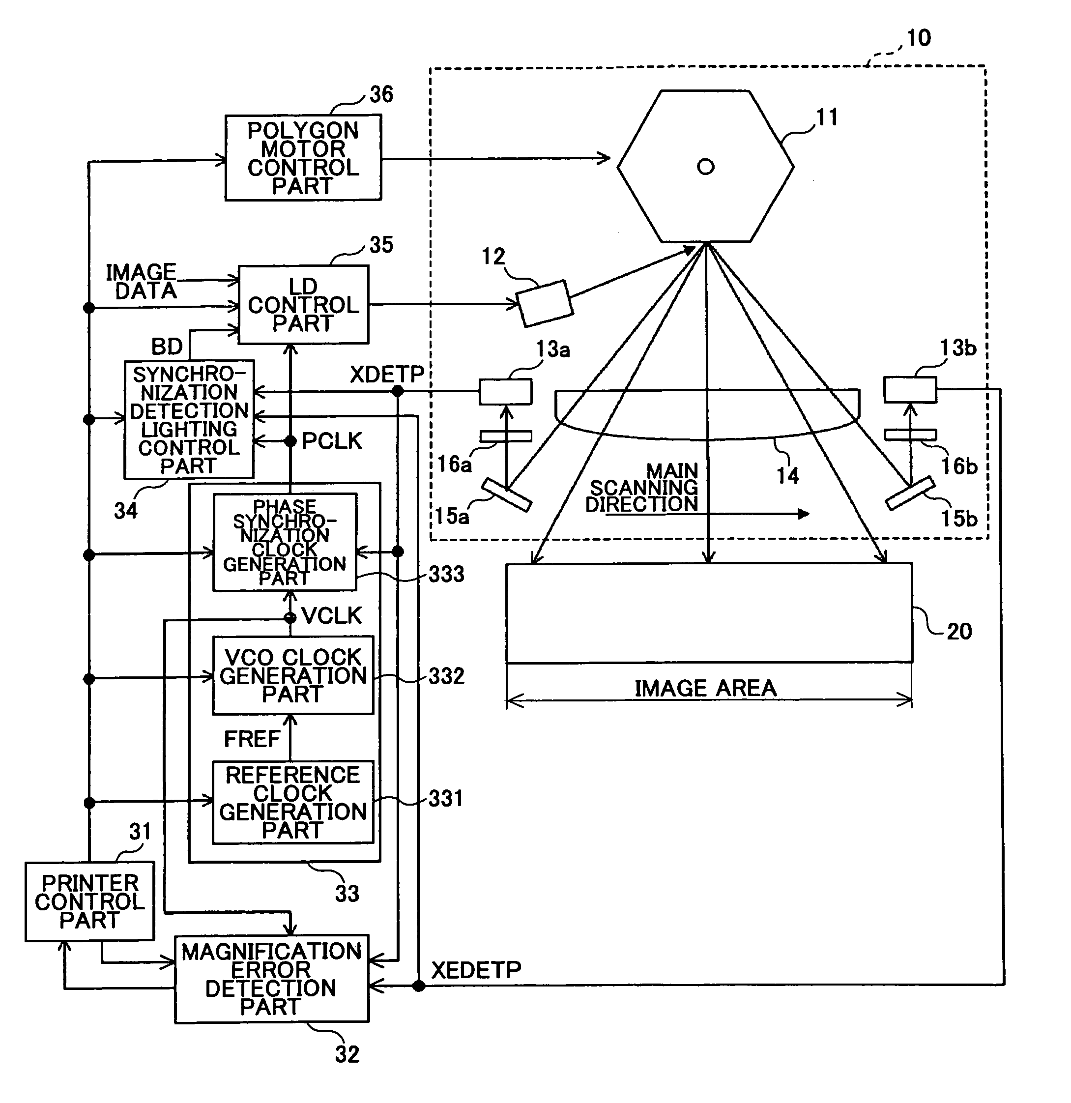
[0057]FIG. 4 is a schematic diagram illustrating a configuration of a light beam scanning device 10, a photosensitive body 20, and their periphery in an image forming apparatus according to a first embodiment of the present invention.
[0058]In the light beam scanning device 10, the light beam of an LD, controlled based on image data to light up, is converted into a parallel beam by a collimator lens (not graphically illustrated), and goes through a cylinder lens (not graphically illustrated) to be deflected by a polygon mirror 11 rotated by a polygon motor 1. Then, the light beam goes through an fθ lens 14 and a barrel toroidal lens (BTL) 2 to be reflected by a deflecting mirror 3 so as to scan the surface of the photosensitive body 20. The BTL 2 performs focusing in the sub scanning direction. That is, the BTL 2 has the function of condensing, and performs positional correction in the sub scanning direction, such as face tangle error correction.
[0059]A charger 4, a development unit ...
second embodiment
[0078]Next, a description is given of an image forming apparatus according to a second embodiment of the present invention. The image forming apparatus of this embodiment is equal to that of the first embodiment in the general configuration of each of the parts of the image forming apparatus, such as the light beam scanning device 10 and the image formation control part, and has the same control flow as that of FIG. 9 of the first embodiment. In the image forming apparatus of the second embodiment, the point-to-point measurement is performed with a maximum amount of light.
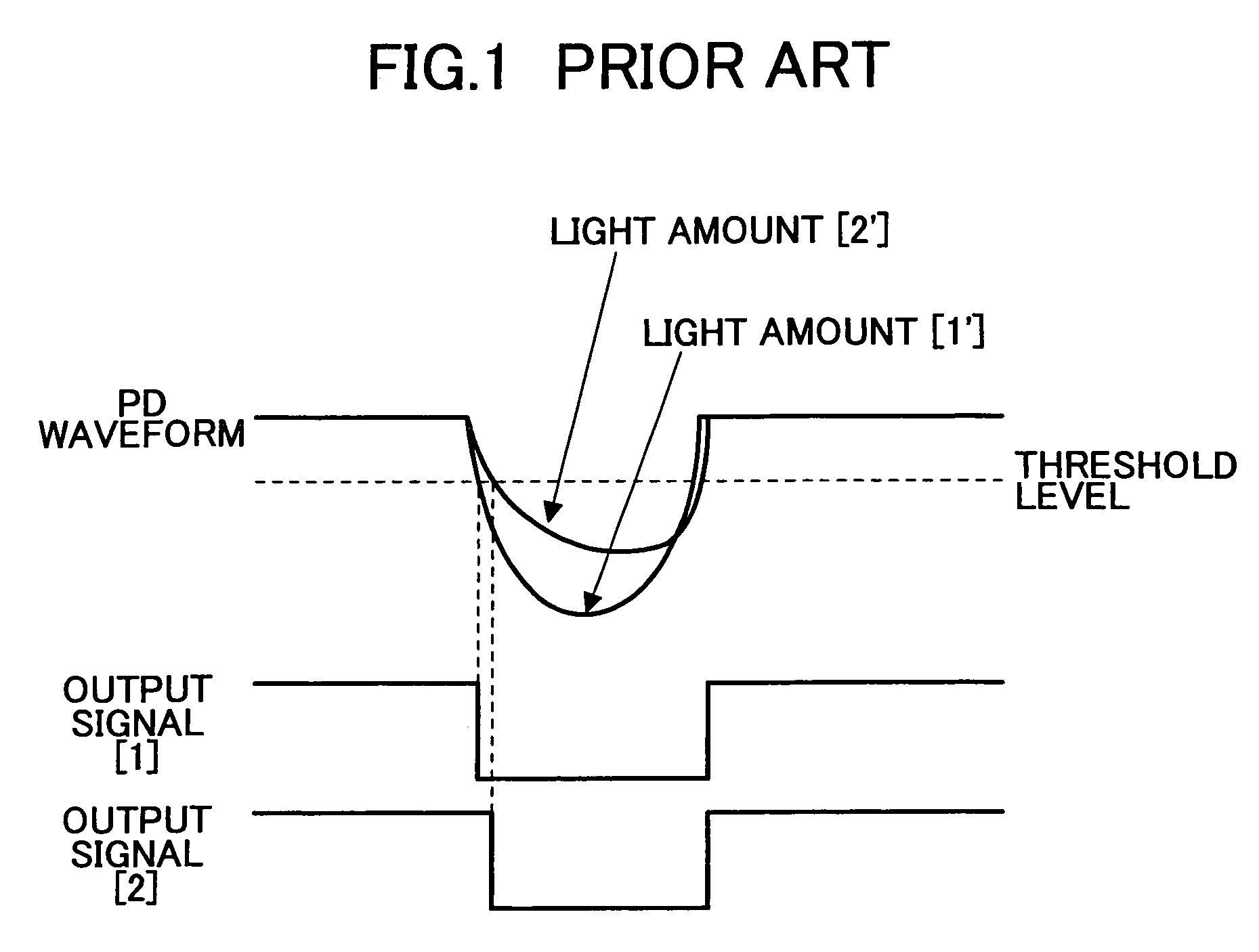
[0079]FIG. 1 illustrates a change in the timing of the output signal (XDETP / XEDETP) due to a change in the amount of light. According to the second embodiment, the amount of light at the time of performing the point-to-point measurement is set to a maximum value (a maximum amount of light possible as a system). As a result, a change in timing with respect to a change in the amount of light can be further controlled...
third embodiment
[0081]Next, a description is given of an image forming apparatus according to a third embodiment of the present invention. The image forming apparatus of this embodiment is equal to that of the first embodiment in the general configuration of each of the parts of the image forming apparatus, such as the light beam scanning device 10 and the image formation control part, and has the same control flow as that of FIG. 9 of the first embodiment. In the image forming apparatus of the third embodiment, the amount of light at the time of performing the point-to-point measurement is set to the medium value of a light amount variation range within which the amount of light is variable.
[0082]FIG. 10 illustrates the transition of the amount of light from a time at which the setting of the amount of light is returned to that for image formation after completion of the point-to-point measurement to a time at which the amount of light reaches the set value. In the case of a system that performs a...
PUM
 Abstract
Description
Claims
Application Information
 - R&D
- Intellectual Property
- Life Sciences
- Materials
- Tech Scout
- Unparalleled Data Quality
- Higher Quality Content
- 60% Fewer Hallucinations
Browse by: Latest US Patents, China's latest patents, Technical Efficacy Thesaurus, Application Domain, Technology Topic, Popular Technical Reports.
© 2025 PatSnap. All rights reserved.Legal|Privacy policy|Modern Slavery Act Transparency Statement|Sitemap|About US| Contact US: help@patsnap.com


