
Floppy disk drive

a technology of floppy disk drive and disk drive, which is applied in the direction of casing/cabinet/drawer details, casing/cabinet/drawer details of electrical apparatus, instruments, etc., can solve the problems of reducing the mechanical strength of the side portions of the disk drive, requiring a large amount of material, etc., and achieves the effect of reducing weight, and reducing the amount of metal material

Inactive Publication Date: 2007-11-13
MITSUMI ELECTRIC CO LTD
View PDF4 Cites 9 Cited by
  • Summary
  • Abstract
  • Description
  • Claims
  • Application Information

AI Technical Summary

Benefits of technology

The present invention provides a floppy disk drive with a reduced amount of metal material and weight, while maintaining sufficient mechanical strength on the side portions of the casing. The drive includes a frame with a bottom portion and left and right walls, which are formed by bending left and right sides of the bottom portion upwardly. The frame is covered by a casing with an upper and lower cover, which are partially overlaid with each other at each side of the casing. The side plates of the upper and lower covers are designed to have size and height that are partially overlaid with the side plates of the upper cover and lower cover, respectively. The invention also includes positioning means for the upper cover, a triplex structure for reinforcing the side portions of the casing, and ridged portions for reinforcing the side plates. The invention further provides a connecting structure for securely attaching the upper and lower covers, and a folded configuration for the ridged portions to prevent deformation of the covers.

Problems solved by technology

This means that the side walls 135 of the frame 13 have to have a large size for securing the height h1, which results in a problem in that a large amount of a material (that is, a material for a metal plate) is necessarily required.
Therefore, if the height of the side walls 135 is simply reduced, there arises a problem in that the mechanical strength at the side portions of the disk drive is lowered.

Method used


Image

  • Floppy disk drive
  • Floppy disk drive
  • Floppy disk drive

Examples


Embodiment Construction

[0040]Hereinbelow, a detailed description of a floppy disk drive according to an embodiment of the present invention will be described with reference to the attached drawings. Since the floppy disk drive of this embodiment is provided with the same internal structures as those of the conventional floppy disk drive shown in FIGS. 9 to 12, the detailed description of the common internal structures are omitted.

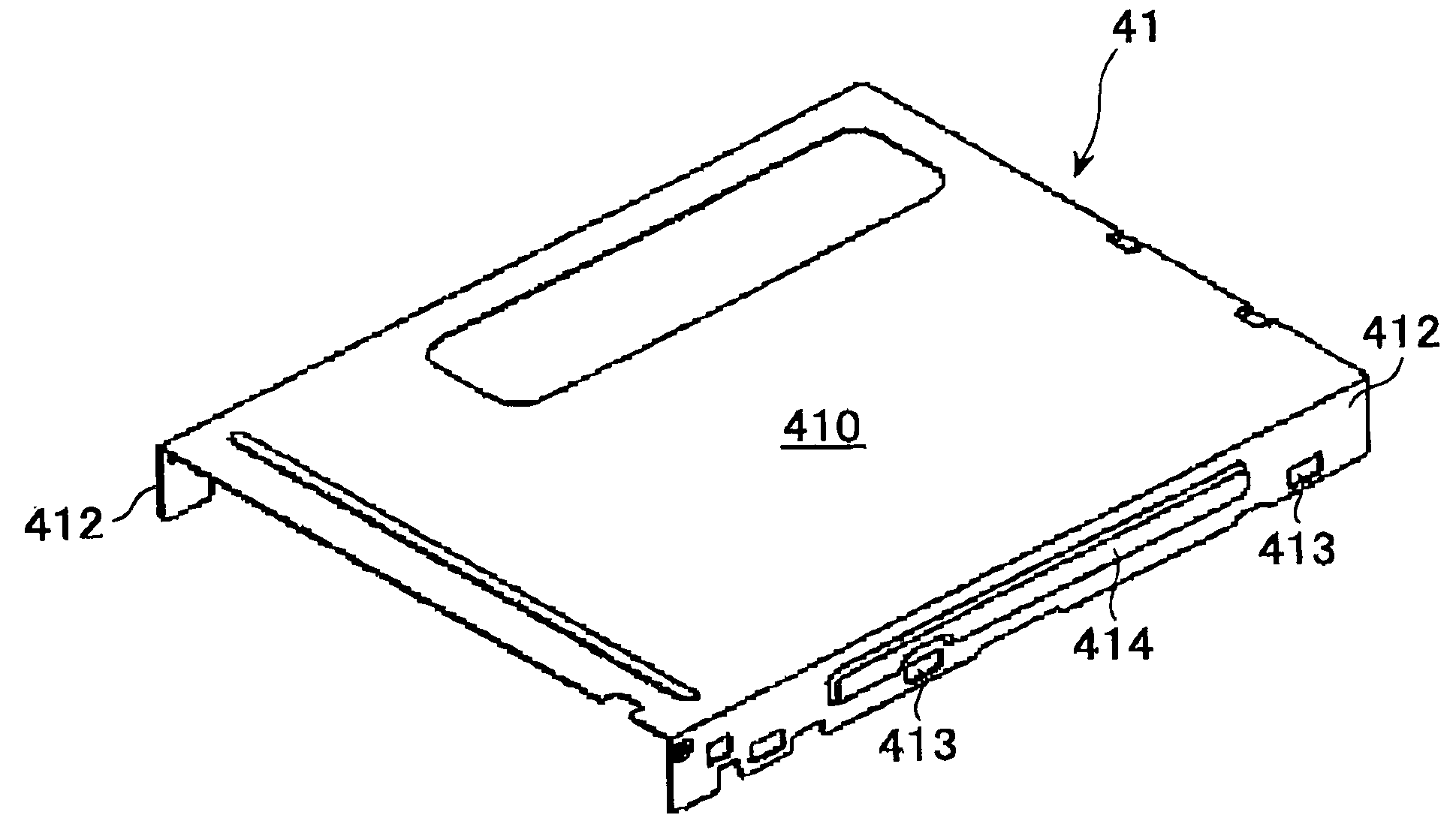
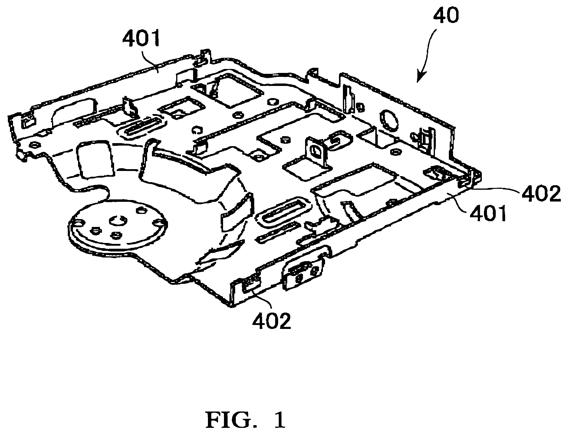
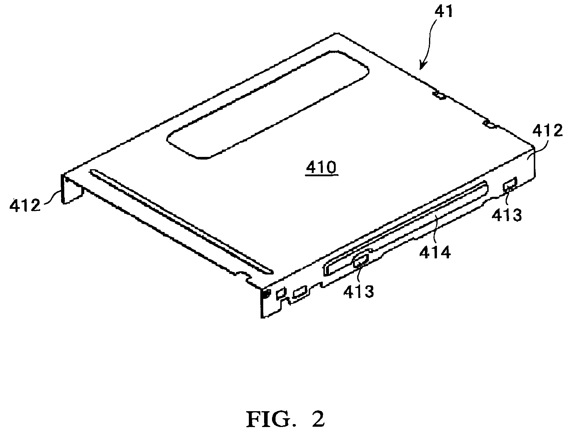
[0041]FIG. 1 is a perspective view of a frame of a floppy disk drive according to an embodiment of the present invention; FIG. 2 is a perspective view of an upper cover of the floppy disk drive according to the embodiment of the present invention; FIG. 3 is a perspective view of a lower cover of the floppy disk drive according to the embodiment of the present invention; FIG. 4 is a side view which shows a state that the lower cover is assembled with the frame; FIG. 5 is a side view of the floppy disk drive according to the embodiment of the present invention; FIG. 6 is a cross se...


PUM

PropertyMeasurementUnit
sizeaaaaaaaaaa
sizeaaaaaaaaaa
heightaaaaaaaaaa

Abstract

A floppy disk drive includes a frame having a bottom portion and left and right walls and a casing for covering the frame. The casing includes an upper cover for covering an upper side of the frame and a lower cover for covering a lower side of the frame, in which the upper cover has a top plate and left and right side plates, and the lower cover has a bottom plate and left and right plates. Each of the side walls of the frame is designed so as to have size and height that are partially overlapped with the side plate of the upper cover and the side plate of the lower cover, respectively, at each side of the casing, thereby providing a triplex structure for reinforcing each side of the casing.

Description

[0001]This application claims priority to Japanese Patent Application No. 2004-194838 filed Jun. 30, 2004, which is hereby expressly incorporated by reference herein in its entirety.BACKGROUND OF THE INVENTION[0002]1. Field of the Invention[0003]This invention relates to a floppy disk drive, and in particular to a structure of a frame and a casing of a floppy disk drive, in which the casing includes upper and lower covers for covering the frame.[0004]2. Description of the Prior Art[0005]As is well known, a floppy disk drive (hereinafter, simply referred to as a “disk drive” on occasions) is an apparatus for writing and reading data to and from a floppy disk which is a disk-shaped magnetic recording medium housed in a predetermined cartridge. Such a floppy disk drive is mounted in laptop personal computers, notebook personal computers or notebook word processors or the like.[0006]Generally, such a floppy disk drive includes magnetic heads for writing and reading data to and from a fl...

Claims


Application Information

Patent Timeline
Patent Type & Authority Patents(United States)
IPC IPC(8): G11B5/016
CPCG11B33/025G11B17/043
Inventor KONNO, MAKOTOKOMATSU, HISATERUKOBAYASHI, NORIYUKIENDO, SHINJI
Owner MITSUMI ELECTRIC CO LTD
Learn More