Switching power supply having dual current feedback

a technology of switching power supply and current feedback, which is applied in the direction of electric variable regulation, process and machine control, instruments, etc., can solve the problems of power supply supply voltage difference, power consumption of the system, and increase the power provided through the transformer to the output signal, so as to achieve a small reserve capacity

Active Publication Date: 2007-11-13
SIEMENS IND INC
View PDF2 Cites 23 Cited by
  • Summary
  • Abstract
  • Description
  • Claims
  • Application Information

AI Technical Summary

Problems solved by technology

Most electronic devices employ circuits that do not directly obtain operating power from mains AC electrical power.
In general, if the feedback signal indicates that the output voltage is too low, presumably due to heavy loading, then the control circuitry may increase the duty cycle of the switched signal generated by switching device, which increases the power provided through the transformer to the output signal.
The power consumption of the system depends on which modules are used in the system.
One problem that arises with the use of parallel power supplies arises from differences in output voltage levels of the supplies.
In some cases, the imbalance of current between the two parallel supplies can be significant.
This is undesirable because one supply will run at full load (hot and stressed) while the other will be nearly unused.
While the resistor can help balance the current between the two supplies by increasing the output impedance, to make the supply look more like a current source rather than a voltage source, the output resistor consumes a significant amount of power, which leads to heat dissipation problems and inefficiencies.

Method used


Image

  • Switching power supply having dual current feedback
  • Switching power supply having dual current feedback
  • Switching power supply having dual current feedback

Examples


Embodiment Construction

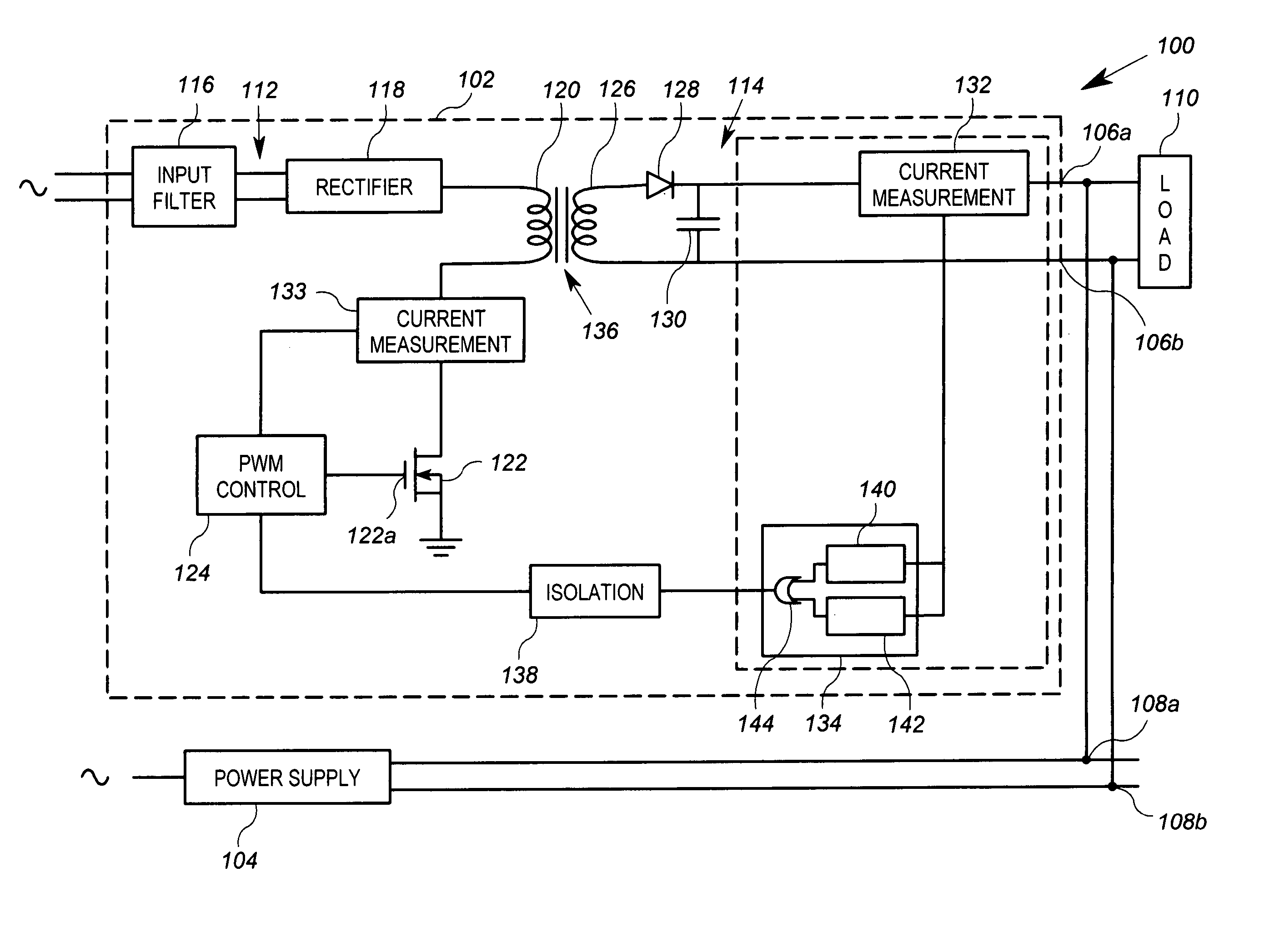
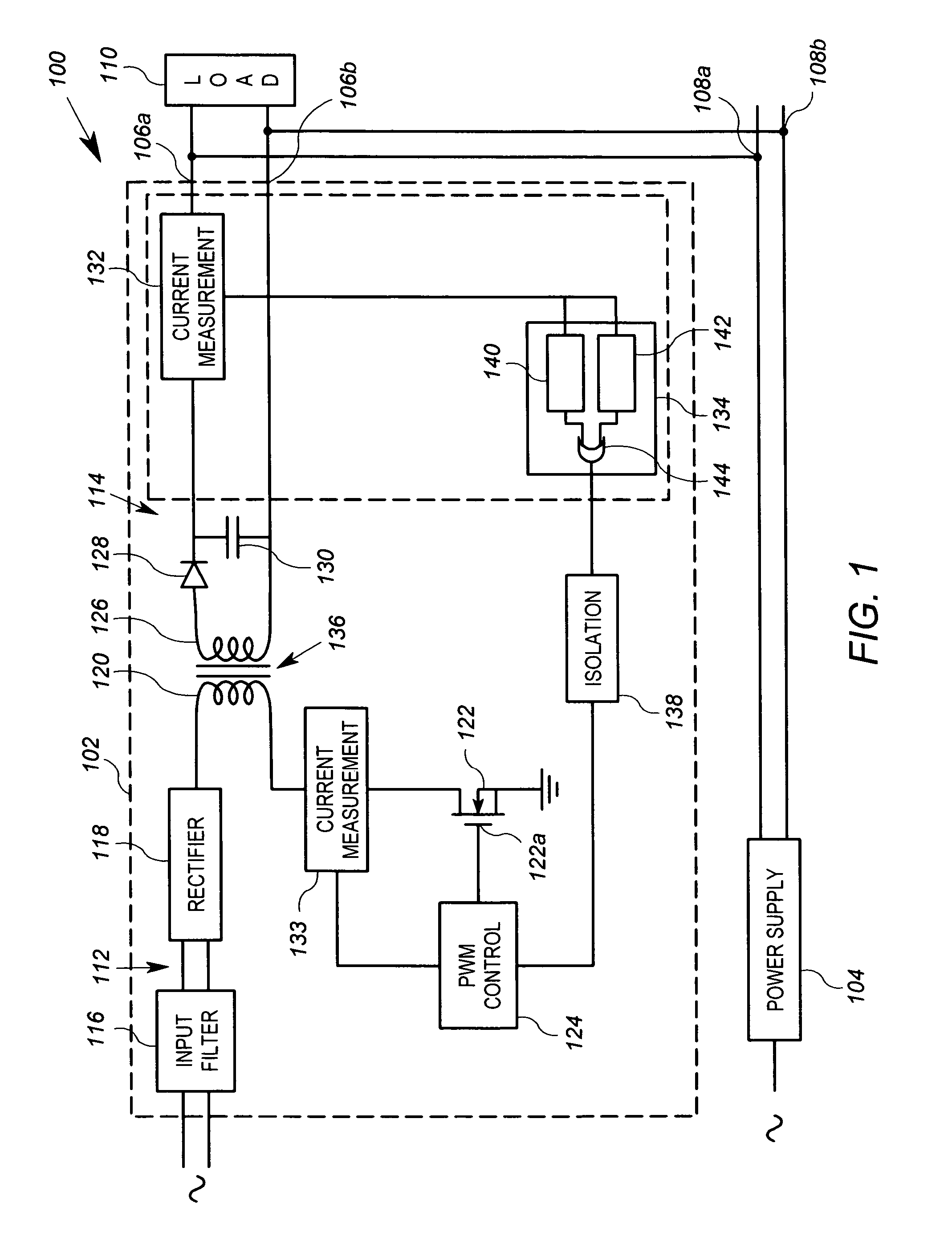
[0018]FIG. 1 shows a parallel power supply arrangement 100 according to embodiments of the invention. The power supply arrangement 100 includes a first power supply 102 and second power supply 104 connected in parallel. In particular, the first power supply 102 includes output terminals 106a, 106b that are connected to output terminals 108a, 108b of the second power supply. The output terminals 106a, 106b are coupled across a load 110, as are the output terminals 108a, 108b. Such a configuration may be used to provide power to a modular system in which power requirements can vary based on the number of modules employed. In such a case, the load 110 would represent the modular system.

[0019]The first power supply 102 includes an arrangement for adjusting its output voltage based on its output current, which is described herebelow. During operation, the first power supply 102 can adjust its output voltage level downward if the output current is relatively high. As discussed generally a...


PUM


Abstract

An arrangement for use in a switching power supply includes a power supply output line, a current sensing circuit, and a feedback circuit. The output line is operably coupled to an output winding of a transformer. The transformer has a first winding operably connected to a switching device configured to be switched in accordance with a first control signal. The current sensing circuit is operable to generate a current signal that is representative of current on the output line. The feedback circuit is operable to generate a feedback signal as a function of the current on the output line. The feedback signal has a first relationship with respect to the current when the current is below a threshold, and has a second relationship with respect to the current when the current is above the threshold.

Description

FIELD OF THE INVENTION[0001]The present invention relates generally to power conversion, and in particular, to a switching power supply having a DC output voltage.BACKGROUND OF THE INVENTION[0002]Most electronic devices employ circuits that do not directly obtain operating power from mains AC electrical power. Instead, electronic devices often require one or more DC supply or bias voltages. In order to generate a regulated DC voltage derived from an AC power source, switching converters are often used. In one common embodiment of a switching converter power supply, an AC input voltage is rectified to a first DC voltage level, which is in turn converted to an output DC voltage level. A DC-DC converter circuit performs the function of converting the first DC voltage level to the output DC voltage level.[0003]There exist a number of different DC-DC converter architectures. A typical DC-DC converter design employs a semiconductor switch in line with the input voltage that is turned on a...

Claims


Application Information

Patent Timeline
Patent Type & Authority Patents(United States)
IPC IPC(8): H02M3/335H02M7/537
CPCH02J1/102H02M3/33507H02M2001/0009H02M1/0009
Inventor CHARLES, DONALD E.
Owner SIEMENS IND INC
Why Eureka
Try Eureka