Receiver processing systems

a technology of receiver processing and receiver, applied in the direction of orthogonal multiplex, radio transmission, electrical equipment, etc., can solve the problems of multiple access interference rise, cdma system is limited by uplink capacity, cdma system may be limited by downlink capacity,

Inactive Publication Date: 2007-11-13
KK TOSHIBA
View PDF33 Cites 27 Cited by
  • Summary
  • Abstract
  • Description
  • Claims
  • Application Information

AI Technical Summary

Benefits of technology

[0043]The skilled person will appreciate that the above described aspects of the invention may be combined to suppress interference contributions arising from more than one source.

Problems solved by technology

Multipath fading arises when a signal from a transmitter to a receiver takes two or more different paths and hence two or more versions of the signals arrive at the receiver at different times and interfere with one another.
It is generally thought that a CDMA system is uplink-limited due to the near-far effect (where the correlation with a strong, nearby signal having an incorrect code is greater than that with a weaker, more distant signal with the correct code).
However a 3G CDMA system may instead be limited by the downlink capacity due to the highly asymmetric services that are envisaged, such as the download of web page and image data from the Internet.
Multiple access interference rises because the spreading codes of signals received from different users are not normally completely orthogonal.
These techniques, while helpful, still leave room for improvement.
Intracell interference arises due to interpath interference and the loss of orthogonality between the channelisation codes.
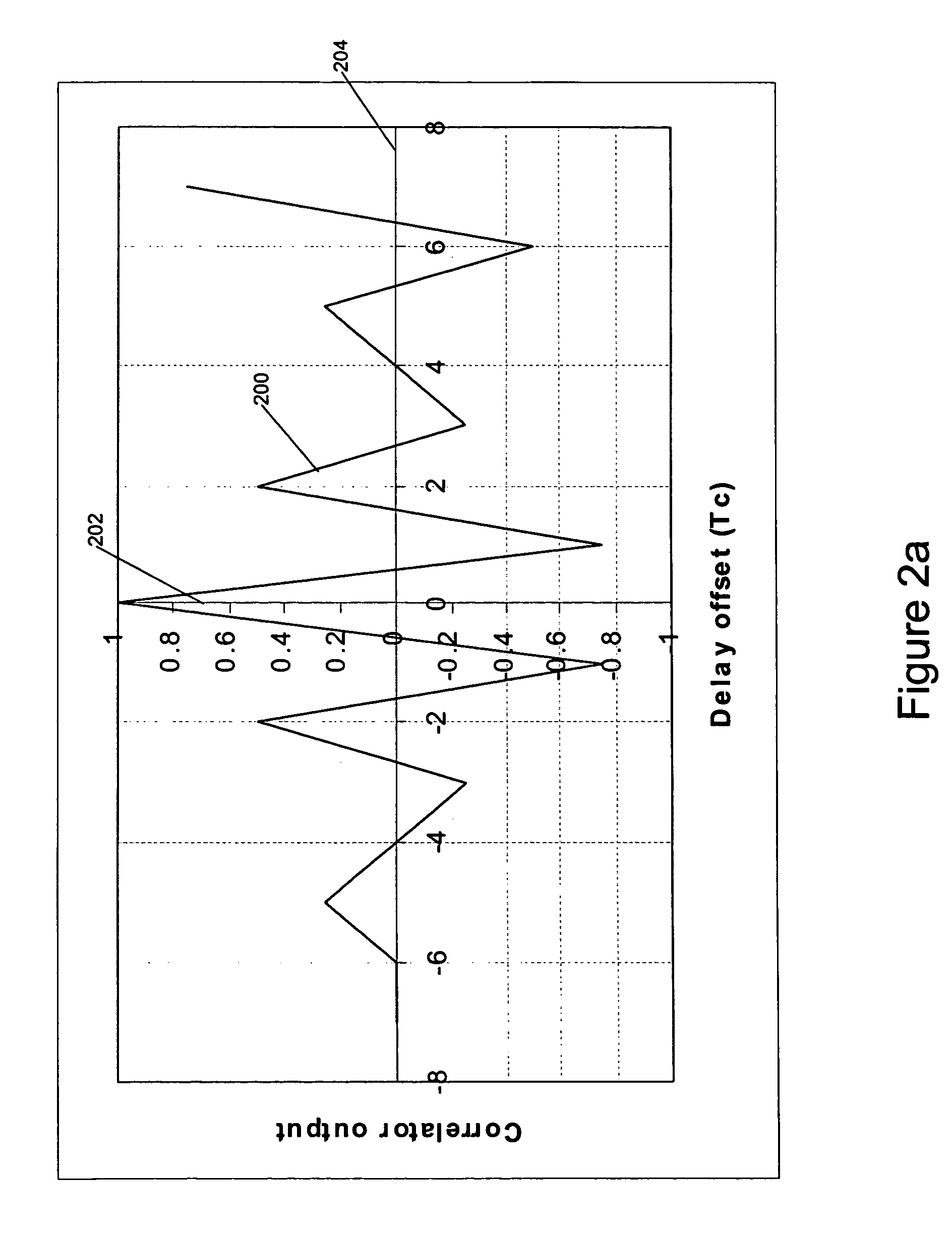
However in the presence of multipath time dispersion the non-zero auto (or cross) space-correlation between different multipath components gives rise to interpath interference.
However in practice the time-dispersive nature of the mobile environment causes a significant loss of orthogonality, as described above, and a consequent increase in MAI.

Method used


Image

  • Receiver processing systems
  • Receiver processing systems
  • Receiver processing systems

Examples


Embodiment Construction

[0070]Without limitation, the types of channel interference from which can be cancelled in the terminal without knowledge of additional spreading codes are, in order of increasing complexity:

[0071]1. Common channels with a known spreading code and known or no modulation such as CPICH and SCH. As the modulating signal is known, this is the simplest approach.

[0072]2. Common channels with a known spreading code modulated by data, such as PCCPCH. To cancel the interference generated by these channels, the channel must be despread and demodulated to determine the transmitted data and then respread to form an estimate of the transmitted signal before the interference can be suppressed from the desired signal. However these channels generally have a significantly higher power and that of the desired dedicated channel from which the interference is to be suppressed, typically 5 dB higher, making it relatively straightforward to detect the channel or channels and suppress the interference.

[0...


PUM


Abstract

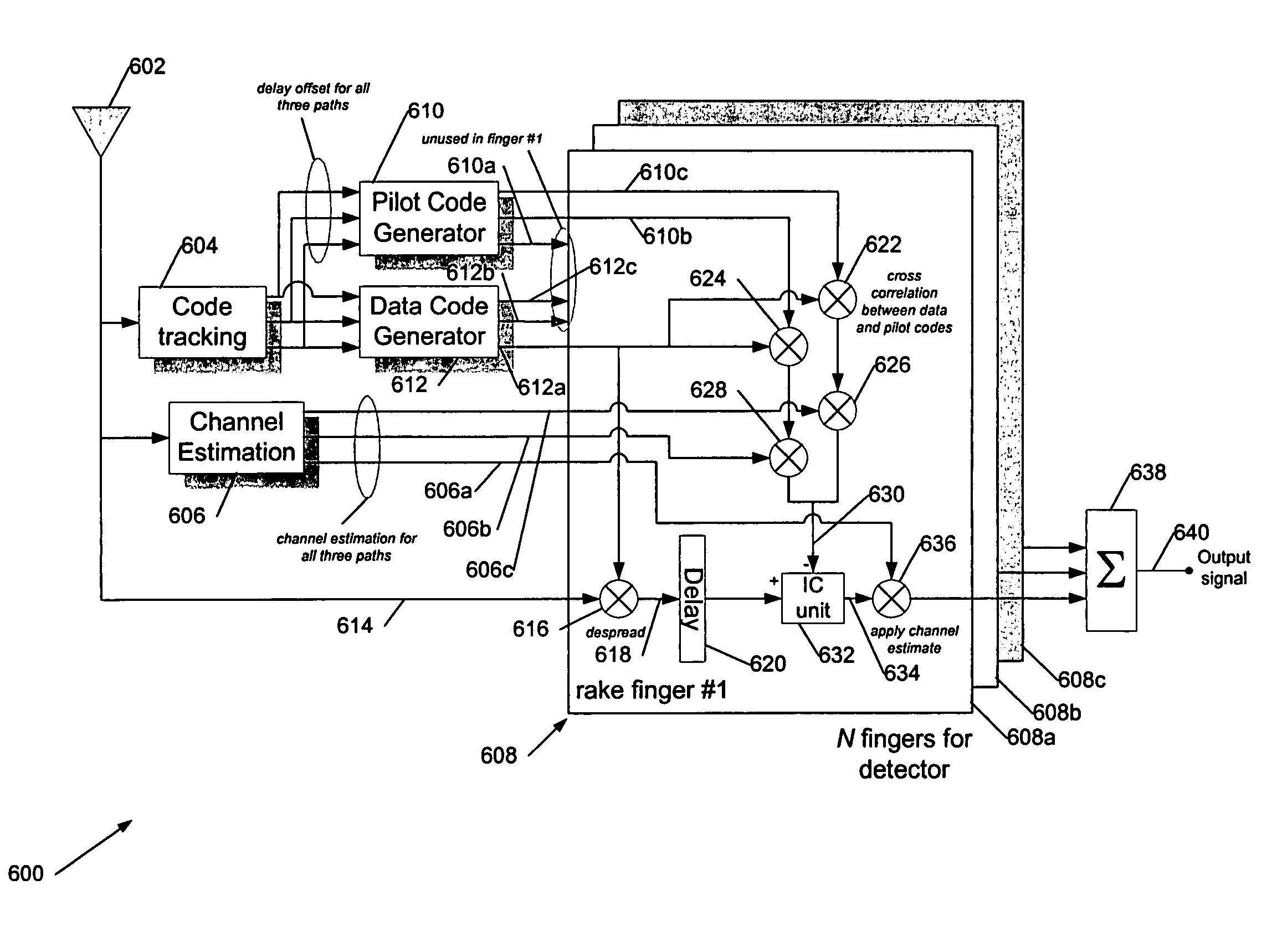
A multicode receiver for receiving data carried by a plurality of spread spectrum signals having a corresponding plurality of spreading codes, the spreading codes being substantially mutually orthogonal, the receiver having intercode interference suppression, the receiver including a multicode spread spectrum receiver to provide a set of data estimates having a plurality of estimates of data carried by the plurality of spread spectrum signals, one estimate for each spread spectrum signal, a plurality of respreaders to respread the plurality of data estimates, a plurality of interference suppressers, at least one for each of the plurality of spreading codes, each at least one interference suppresser for each code being configured to suppress respread data estimates for the spread spectrum signals of the other codes, from a received signal, a plurality of rake fingers each having the plurality of interference suppressers, and a plurality of rake combiners, one for each of the plurality of spreading codes.

Description

FIELD OF THE INVENTION[0001]This invention generally relates to architectures, systems and methods for reducing interference in spread spectrum receivers, particularly rake receivers. The invention has applications in digital mobile communications systems, especially third generation (3G) systems.BACKGROUND OF THE INVENTION[0002]Third generation mobile phone networks use CDMA (Code Division Multiple Access) spread spectrum signals for communicating across the radio interface between a mobile station and a base station. These 3G networks, (and also so-called 2.5G networks), are encompassed by the International Mobile Telecommunications IMT-2000 standard (www.ituint, hereby incorporated by reference). Third generation technology uses CDMA (Code Division Multiple Access) and the IMT-2000 standard contemplates three main modes of operation, W-CDMA (Wide band CDMA) direct spread FDD (Frequency Division Duplex) in Europe and Japan, CDMA-2000 multicarrier FDD for the USA, and TD-CDMA (Time...

Claims


Application Information

Patent Timeline
Patent Type & Authority Patents(United States)
IPC IPC(8): H04B1/69H04B1/707H04J11/00
CPCH04B1/7107H04B1/71075H04J13/0077
Inventor FITTON, MICHAEL PHILIPRIZVI, KHURRAM ALICHOW, YUK CHING
Owner KK TOSHIBA
Why Eureka
Try Eureka