System for and method of power efficient electrical tissue stimulation

a technology of electrical tissue and power-efficient operation, which is applied in the field of medical devices capable of producing tissue or nerve stimulating pulses, can solve the problems of inefficiency of typical circuit techniques in driving this type of electrodes, and none of the electrodes and other components are recovered after stimulation, so as to reduce the power required for effective stimulation and power-efficient operation

Active Publication Date: 2007-11-13
MASSACHUSETTS INST OF TECH
View PDF12 Cites 33 Cited by
  • Summary
  • Abstract
  • Description
  • Claims
  • Application Information

AI Technical Summary

Benefits of technology

[0012]The present invention provides a variety of circuits and techniques for power-efficient operation of, and energy recovery from, tissue-stimulating ele

Problems solved by technology

Typical circuit techniques are very inefficient when driving this type of electrode, often using more than twice the necessary energy during the first phase o

Method used


Image

  • System for and method of power efficient electrical tissue stimulation
  • System for and method of power efficient electrical tissue stimulation
  • System for and method of power efficient electrical tissue stimulation

Examples


first embodiment

Power Efficient Electrode Supply: First Embodiment

[0074]In reality, a voltage supply that follows the step-ramp pattern in FIG. 6A or 6B is very difficult to build. But an approximation to those patterns can be made by switching between a number of different voltage supplies 176A-C, as shown schematically in FIG. 7. A typical implementation for a power efficient voltage supply 175, as shown, might use three voltage sources 176A-C for each phase 110, 114. The total number of voltage sources in that case could be held to four if the middle voltage source 176B were used in both phases. This is shown in the waveforms of FIGS. 8A and 8B, with three negative voltages and one positive voltage. The use of a greater number of voltage levels will yield a closer approximation to the minimum required power, but at a cost of increased system complexity. The dashed lines represent the optimal electrode voltage 178 and optimal current 180 waveforms for minimal power dissipation. One of the solid l...

second embodiment

Power Efficient Electrode Supply: Second Embodiment

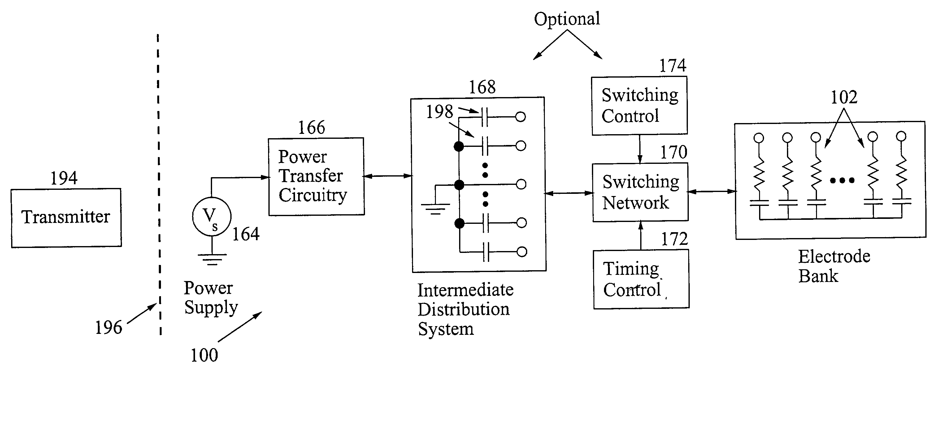
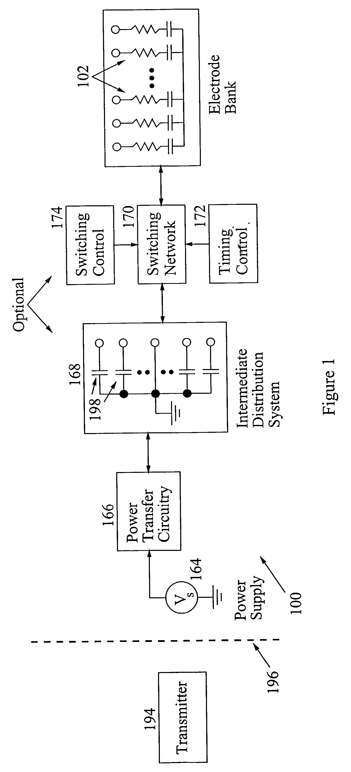
[0075]Another embodiment of a power efficient electrode supply 175 is illustrated in FIG. 9. In this configuration, a ramping voltage 163 may be made available to charge electrode 102 (or multiple electrodes not shown) by driving a constant current from a power supply 164 into a storage capacitor 165 by means of power transfer circuitry 166. Capacitor 165 comprises a portion of an intermediate distribution system (IDS) 168, which is represented in FIG. 1 as a bank of storage capacitors. Storage capacitor 165 will be the only capacitor connected to the electrode being stimulated during a single constant-current phase. Switch network 170 establishes and interrupts connections between the ramping capacitor 165 and the electrodes 102 to be stimulated. Capacitor 165 can be charged to give a pseudo-ramping voltage by power transfer circuitry 166. There will be some ripple in the ramp, but it can be kept small.

[0076]Power transfer circuitr...


PUM


Abstract

Circuitry for and method of power efficient operation of, and energy recovery from, tissue-stimulating electrodes having high charge capacities. Post-stimulation energy is recovered from the electrodes through a variety of techniques into circuit elements such as other electrodes, an intermediate distribution system, a power supply or any other elements, through the use of sequential switching. Energy is also recoverable from the intermediate distribution system, which preferably is comprised of one or more storage capacitors operating a different voltages. Efficient power transfer among circuit elements is effected by transferring energy while limiting element-element voltage differences and/or voltage differences between the elements and the capacitances of the electrodes.

Description

[0001]This application claims the benefit of priority to U.S. Provisional Application No. 60 / 328,346 filed Oct. 10, 2001.FIELD OF THE INVENTION[0002]The present invention relates to the field of medical devices, and more particularly relates to medical devices capable of generation of tissue or nerve stimulating pulses. Even more particularly, the present invention relates to efficient power utilization in, and energy recovery from, electrodes of implantable prostheses, such as retinal or cochlear stimulators.BACKGROUND OF THE INVENTION[0003]Devices for electrically stimulating tissue, including cochlear implants, pacemakers, muscle and spinal cord stimulators, have been in use for decades. Retinal prostheses that might assist some of the estimated 10 million people worldwide who are blind as a result of degenerative retinal diseases, such as age-related macular degeneration and retinitis pigmentosa, are under development based on the concept of replacing photoreceptor function with...

Claims


Application Information

Patent Timeline
IPC IPC(8): A61N1/18A61N1/08A61N1/36A61N1/378
CPCA61N1/0541A61N1/08A61N1/0543A61N1/3787
Inventor KELLY, SHAWNRIZZO, JOSEPHWYATT, JOHN
Owner MASSACHUSETTS INST OF TECH
Why Eureka
Try Eureka