Tufting machine

a technology of tufting machine and tufting plate, which is applied in the direction of embroidering machine, sewing apparatus, textiles and paper, etc., can solve the problems of dividing plate oscillation with the hook, obvious visual defect in the product,

Active Publication Date: 2007-11-20
SOC DINVESTMENT MOSELLE SA
View PDF9 Cites 32 Cited by
  • Summary
  • Abstract
  • Description
  • Claims
  • Application Information

AI Technical Summary

Problems solved by technology

When any of these events occur, there is an obvious visual defect in the product.
However, in this case, the dividing plates would oscillate with the hooks.

Method used


Image

  • Tufting machine
  • Tufting machine
  • Tufting machine

Examples


Embodiment Construction

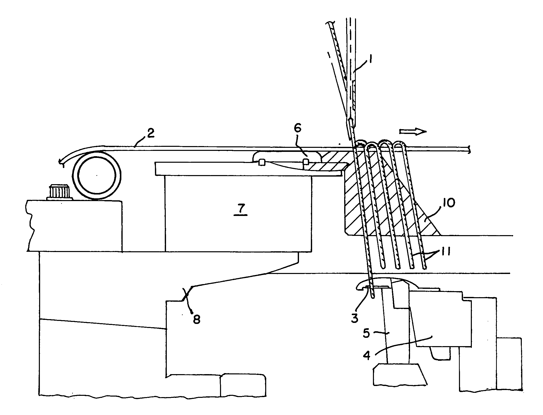
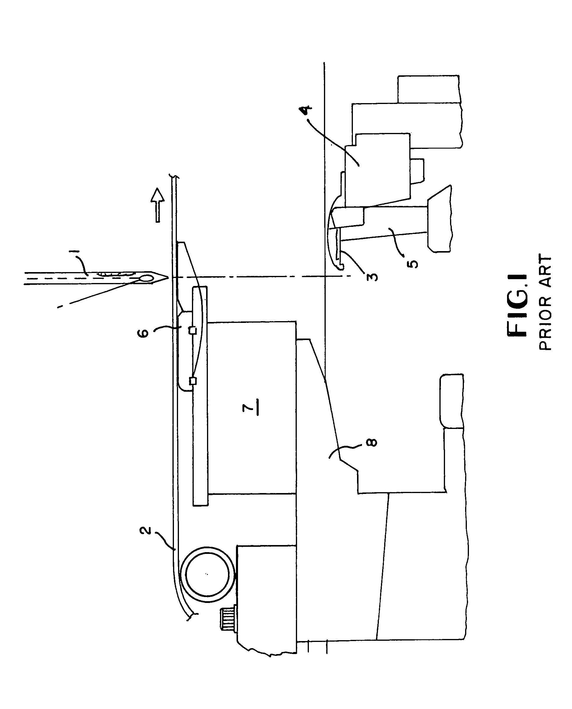
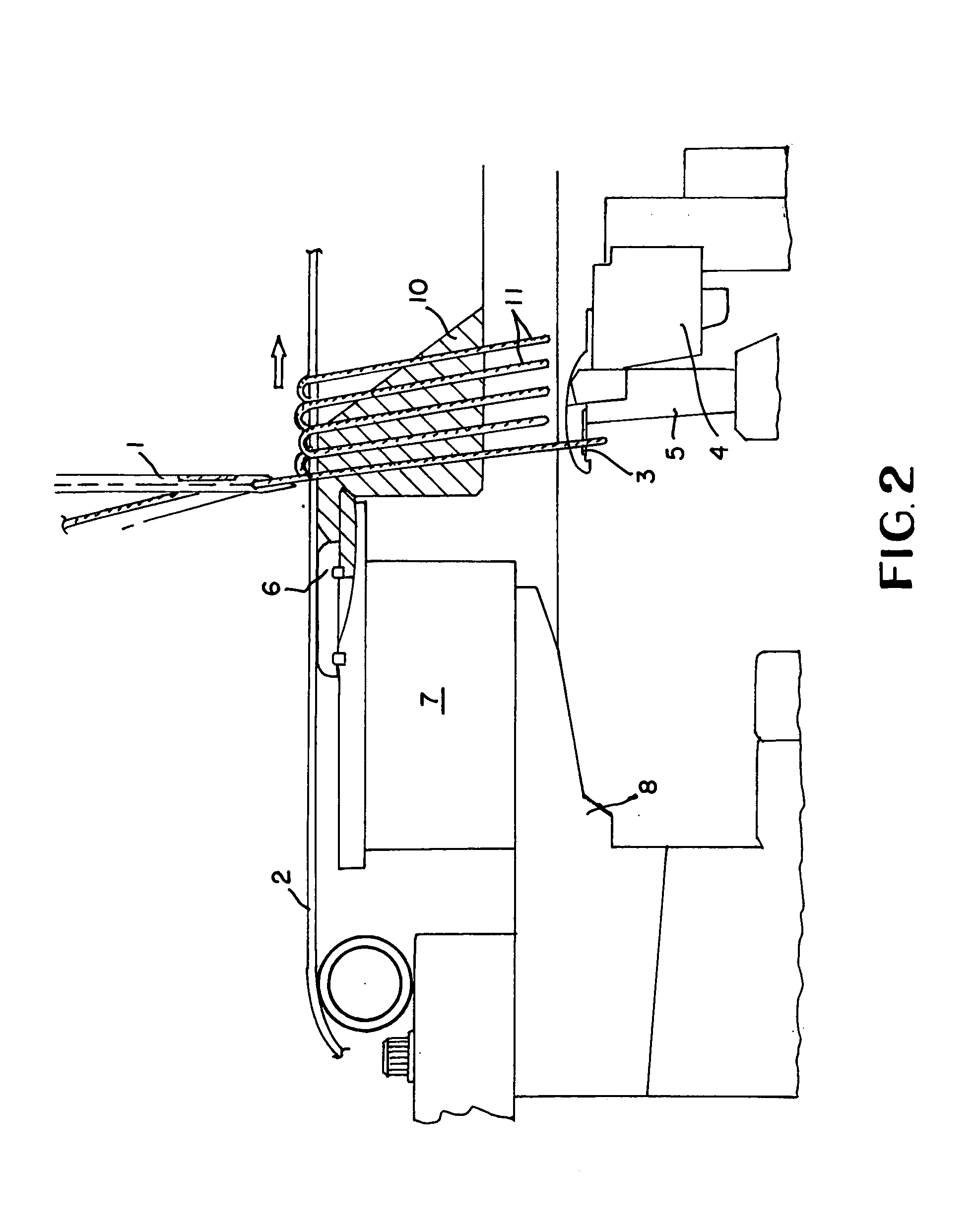
[0014]The components of a tufting machine as shown in FIG. 1 are well known in the art. The tufting machine has a plurality of needles 1 arranged in at least one row perpendicular to the plane of FIG. 1 which reciprocate vertically. A backing material 2 passes through the machine, in this case, since the machine is a cut-pile tufting machine, from left to right perpendicular to the direction of needle reciprocation. A hook 3 associated with each needle is provided below the backing material on a hook bar 4 which reciprocates or more correctly oscillates the hook in a generally horizontal sense. A knife 5 in a cut-pile machine oscillates with respect to each hook to cut the loops of yarn formed on the hook. The present invention is also applicable to loop pile machines (i.e., where no knives are provided and the hooks 5 are replaced with loopers) which seize and shed the loops since the hook faces the opposite direction to that illustrated in FIG. 1. However, in this case, the moveme...


PUM


Abstract

A tufting machine for producing pile fabric having a pile height of approximately at least 50 mm has divider plates between adjacent needles to prevent yarn loops and especially the legs of cut loops from becoming trapped between an adjacent needle and its associated yarn feed. The divider plates may take the form of plates forming an extension of the fingers of the needle plate between each pair of which a needle reciprocates and may be mounted on a block on the bed plate beneath the needle plate, or may be plates upstanding from the hook bar.

Description

BACKGROUND OF THE INVENTION[0001]The present invention relates to tufting machines, and in particular, to tufting machines capable of producing a high-pile tufted product. Such machines may be used to produce artificial grass, and have been used to produce shag carpet.[0002]During the tufting of a high-pile, cut pile material, the tuft legs of the yarn become extremely lively or springy immediately after being cut. This is particularly true in regard to polypropylene yarns. Accordingly, the free ends often may be pulled back through the backing material as they become trapped between neighboring needles and their associated yarn feed. Additionally, the cut yarn may enter the adjacent needle eye, and sometimes the adjacent needle may even sew through a previously formed loop in the case of loop pile. When any of these events occur, there is an obvious visual defect in the product.[0003]According to the present invention, a tufting machine is provided which comprises a plurality of al...

Claims


Application Information

Patent Timeline
Patent Type & Authority Patents(United States)
IPC IPC(8): D05C15/14D05C15/00D05C15/16
CPCD05C15/16D05C15/14
Inventor BEVERLY, IAN
Owner SOC DINVESTMENT MOSELLE SA
Why Eureka
Try Eureka