Drive unit, and a powered vehicle

a technology of driving unit and powered vehicle, which is applied in the direction of vehicle position/course/altitude control, process and machine control, instruments, etc., can solve the problems of lack of accuracy and navigation, limited automatic system for doing this, poor radio communication, etc., and achieve the effect of eliminating slippag

Inactive Publication Date: 2007-11-20
WICREATIONS BVBA
View PDF14 Cites 19 Cited by
  • Summary
  • Abstract
  • Description
  • Claims
  • Application Information

AI Technical Summary

Benefits of technology

[0008]According to the present invention there is provided in a first aspect a drive unit comprising a rolling means intended to be in frictional engagement with a surface over which said drive unit is intended to move. The drive unit also comprises a first driving means and a second driving means, co-operatively operable to provide both propulsion and steering of said drive unit while eliminating slippage between said rolling means and said surface. The first drive means is arranged on a rotatable support means rotatable about a center axis and operable to rotate said rolling means about a rolling axis, wherein said rolling means is displaced a predetermined distance from said center axis. The second driving means is operable to rotate said support means about said center axis. This drive unit eliminates the slippage between the rolling means and said surface. This is achieved without the use of any special floor materials or without limiting the types of movement the drive unit can make.
[0026]Furthermore, it is an advantage in the context if said powered vehicle also comprises a wireless communication means for receiving control signals from a remote computer system to control said drive units.

Problems solved by technology

Automated systems for doing this have been limited by poor radio communication, lack of accuracy and navigation, high noise and high costs.
One main disadvantage with the stage wagon according to the document U.S. Pat. No. 5,823,884 is that it causes damage to the floor surface caused by slippage, due to rotation of the drive wheel at slow speeds or at standstill.
One way of trying to eliminate this problem is the use of special floor materials or require the wagon to move in order to rotate the wheel, limiting the types of movement the wagon can make.
However, these solutions result in other problems as is clear from the statements made above.

Method used


Image

  • Drive unit, and a powered vehicle
  • Drive unit, and a powered vehicle
  • Drive unit, and a powered vehicle

Examples


Embodiment Construction

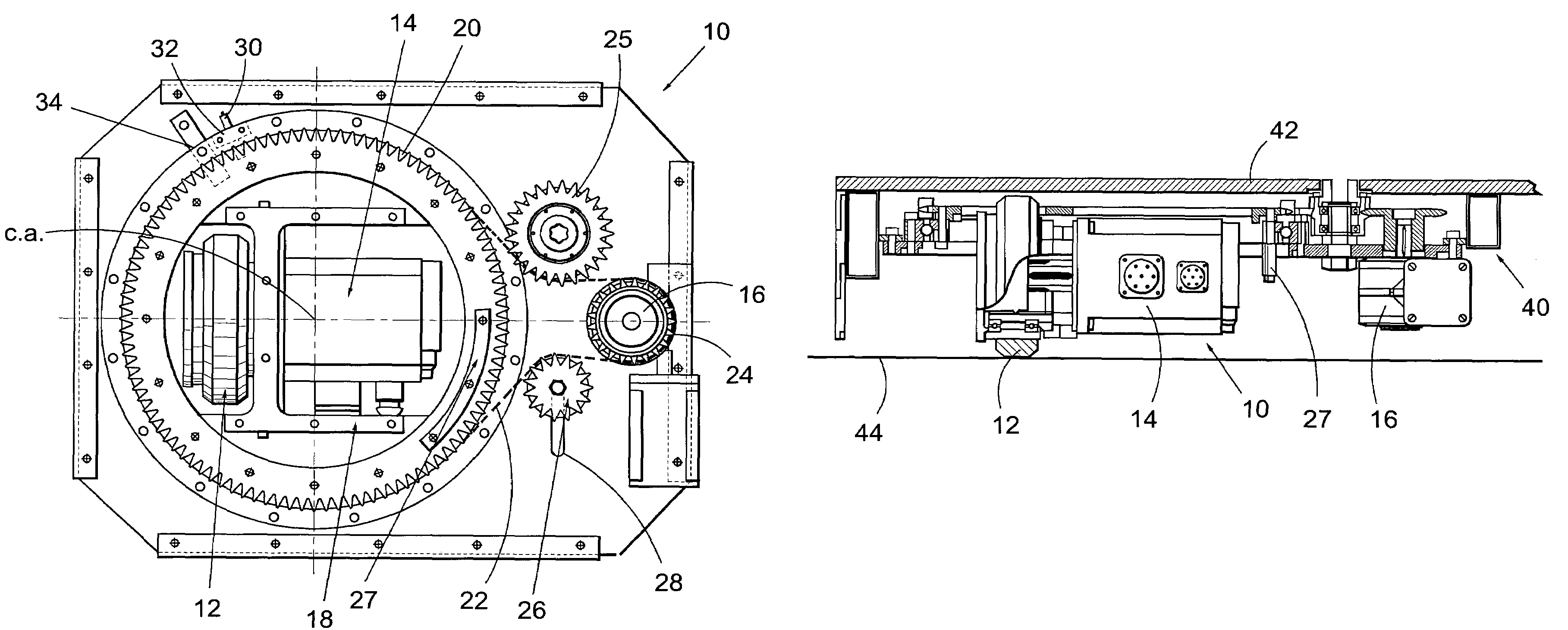
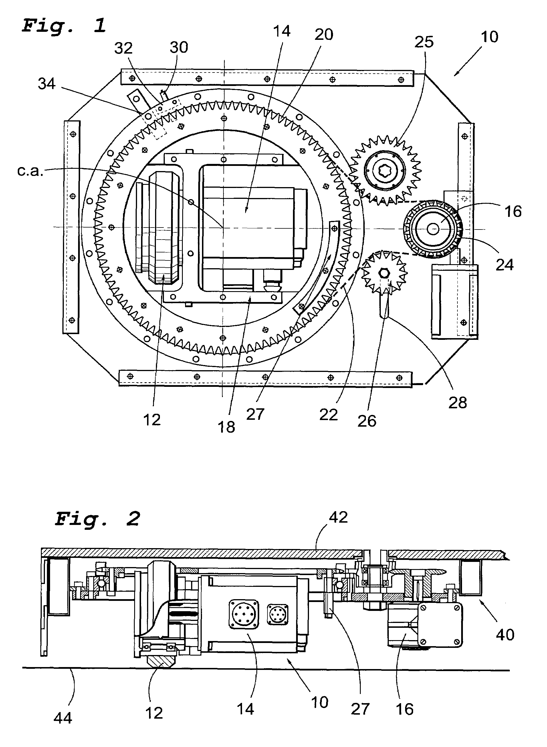
[0032]FIG. 1 shows a side view from above of a drive unit 10 according to the present invention. The drive unit 10 comprises a rolling means 12 intended to be in frictional engagement with a surface (see FIG. 2) over which said drive unit 10 is intended to move. Preferably, said rolling means 12 is a wheel 12. The driving unit 10 also comprises a first driving means 14, and a second driving means 16, co-operatively operable to provide both propulsion and steering of said drive unit 10. The first driving means 14 is arranged on a rotatable support means 18 rotatable about a center axis, c.a. The first driving means 14 is operable to rotate said rolling means 12 about a rolling axis (see FIG. 2). The rolling axis is perpendicular to said center axis, c.a. As is apparent from FIG. 1, the rolling means 12 is displaced a predetermined distance from the center axis, c.a. The second driving means 16 is operable to rotate the support means 18 about said center axis, c.a. In one preferred em...


PUM


Abstract

The present invention relates to a drive unit (10) comprising a rolling means (12) intended to be infrictional engagement with a surface over which said drive unit (10) is intended to move. The drive unit (10) also comprises a first driving means (14) and a second driving means (16), co-operatively operable to provide both propulsion and steering of said drive unit (10) while eliminating slippage between said rolling means (12) and said surface. The first driving means (14) is arranged on a rotatable support means (18) rotatable about a center axis (c.a.) and is operable to rotate said rolling (12) about a roling axis. rolling means (12) is displaced a predetermined distance from said center axis (c.a.), and the second driving means (16) is operable rotate the support means (18) about said center axis (c.a.).

Description

[0001]This application is the US national phase of international application PCT / SE03 / 00109 filed 22 Jan. 2003, which designated the US and claims priority to SE Application No. 0200201-2, filed 22 Jan. 2002. The entire contents of these applications are incorporated herein by reference.[0002]The present invention relates in a first aspect to a drive unit.[0003]In a second aspect the present invention relates to a powered vehicle.DESCRIPTION OF THE RELATED ART[0004]The theatre has automated much of the equipment used for the movement of scenery and lighting. Most of stage activity involves simply moving scenery about the stage. Automated systems for doing this have been limited by poor radio communication, lack of accuracy and navigation, high noise and high costs.[0005]The document U.S. Pat. No. 5,823,884 discloses a powered stage wagon comprising a chassis to which there is mounted a plurality of rolling support means, each of which is located at a respective corner of the chassis...

Claims


Application Information

Patent Timeline
Patent Type & Authority Patents(United States)
IPC IPC(8): B60K1/02B60K7/00B60K17/30B62D7/02G05D1/02
CPCB60K7/0007B60K17/303G05D1/0282B62D7/02B60K17/046B60K2007/0076B60L2220/46B60K2007/0046
Inventor PHILIPSON, NIKLAS
Owner WICREATIONS BVBA
Why Eureka
Try Eureka