AI technical title is built by Patsnap AI team. It summarizes the technical point description of the patent document.
a technology of retaining rings and threaded rings, which is applied in the direction of burners, electric spraying apparatuses, ways, etc., can solve the problems of nozzles, nozzle distortion, and difficulty in removing threaded rings, and adversely affecting the quality of atomization of coating materials being dispensed
Inactive Publication Date: 2007-11-20
CARLISLE FLUID TECH INC
View PDF105 Cites 61 Cited by
Summary
Abstract
Description
Claims
Application Information
AI Technical Summary
This helps you quickly interpret patents by identifying the three key elements:
Problems solved by technology
Method used
Benefits of technology
Problems solved by technology
A problem associated with such threaded rings is that they can be overtightened.
Overtightening may make it difficult to remove the threaded ring if it should be necessary or desirable to remove the air cap, nozzle, or the like which the threaded ring is holding on the spray gun, for example, to clean it, repair it or replace it.
Additionally, overtightening the air cap, nozzle, or the like can distort the shape of the air cap, nozzle, or the like.
Changing the spatial relationships of such orifices can adversely impact the quality of atomization of the coating material being dispensed from such a spray gun.
This, in turn, can adversely impact the coating provided by the dispensed coating material.
Method used
Image
Click on the blue label to locate the original text in one second.
Reading with bidirectional positioning of images and text.
Examples
Embodiment Construction
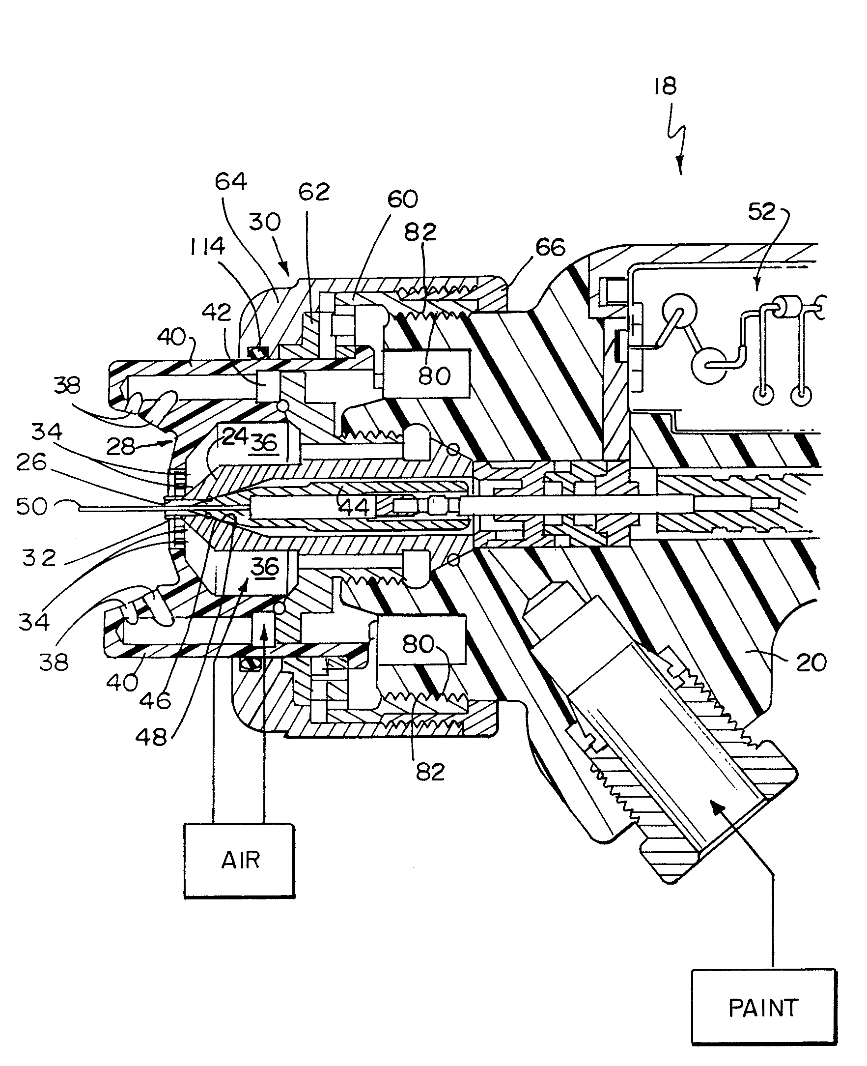
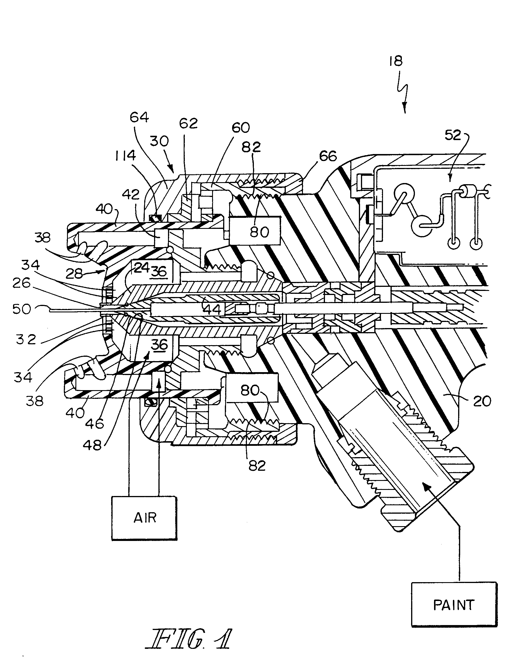
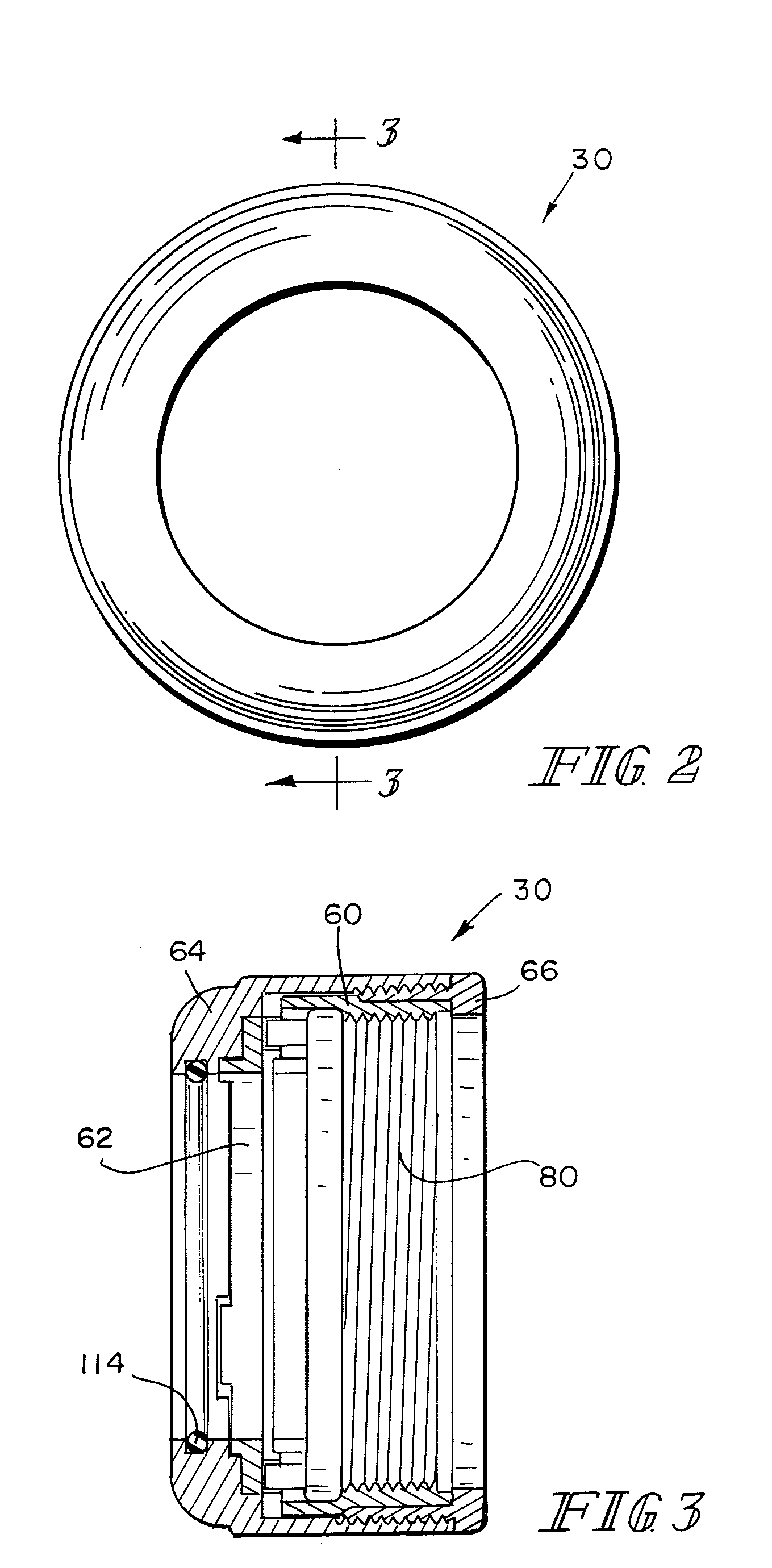
[0037]Referring to FIG. 1, a spray gun 18 includes a spray gun body 20 housing a nozzle 24. Nozzle 24 is disposed at the front end of the gun body 20 to dispense fluent coating material (hereinafter sometimes paint) from a front end opening 26. An air cap 28 is attached to the front end of the gun body 20 by a retaining ring 30 constructed according to the present invention. The air cap 28 has a central atomizing air orifice 32 and a plurality of atomizing air orifices 34 surrounding the central orifice 32. These orifices communicate with a gallery 36 which is coupled to a supply of compressed air. Shaping air orifices 38 are provided on air horns 40 which extend forward from diametrically opposite sides of the air cap 28. The shaping air orifices 38 communicate with a shaping air supply gallery 42 which is also coupled to a supply of compressed air. Shaping air orifices 38 provide air for shaping a spray pattern of paint flowing from the nozzle 24 and atomized by air from atomizing...
PUM
Abstract
A retaining ring for a coating material dispenser including a nozzle for the discharge of coating material and a cap having a plurality of orifices arrayed in a spatial orientation with respect to the nozzle to supply a flow of gas or a mixture of gases to aid in dispensing of the coating material from the nozzle. The retaining ring is adapted for retaining the cap on the coating material dispenser with the plurality of orifices in the spatial orientation. The retaining ring includes first and second members. The second member is adapted for coupling to the coating material dispenser. The first member includes a first torque limiting driving member. The second member includes a second torque limiting driven member for engaging the first torque limiting driving member to limit the torque which the second member can apply to the coating material dispenser in response to manipulation of the first member.
Description
FIELD OF THE INVENTION [0001]This invention relates to threaded retainers. It is disclosed in the context of threaded retainers for retaining air caps, nozzles and the like on the front ends of coating dispensing devices (hereinafter sometimes spray guns). However, it is believed to be useful in other applications as well.BACKGROUND OF THE INVENTION [0002]Various types of manual and automatic spray guns are known. There are, for example, the manual spray guns illustrated and described in the following listed U.S. Patents and published applications: 2003 / 0006322; U.S. Pat. Nos. 6,712,292; 6,698,670; 6,669,112; 6,572,029; 6,460,787; 6,402,058; RE36,378; 6,276,616; 6,189,809; 6,179,223; 5,836,517; 5,829,679; 5,803,313; RE35,769; 5,639,027; 5,618,001; 5,582,350; 5,553,788; 5,400,971; 5,395,054; D349,559; 5,351,887; 5,332,159; 5,332,156; 5,330,108; 5,303,865; 5,299,740; 5,289,974; 5,284,301; 5,284,299; 5,236,129; 5,209,405; 5,209,365; 5,178,330; 5,119,992; 5,118,080; 5,180,104; D325,241;...
Claims
Application Information
Patent Timeline
Application Date:The date an application was filed.
Publication Date:The date a patent or application was officially published.
First Publication Date:The earliest publication date of a patent with the same application number.
Issue Date:Publication date of the patent grant document.
PCT Entry Date:The Entry date of PCT National Phase.
Estimated Expiry Date:The statutory expiry date of a patent right according to the Patent Law, and it is the longest term of protection that the patent right can achieve without the termination of the patent right due to other reasons(Term extension factor has been taken into account ).
Invalid Date:Actual expiry date is based on effective date or publication date of legal transaction data of invalid patent.

