Systems and methods for navigation and control of an implant positioning device

a positioning device and computer-aided technology, applied in the field of semi-active surgical robotics, can solve problems such as the loss of implants, the wear and tear of components, and the need for revisions

Inactive Publication Date: 2014-05-15
BLUE BELT TECH
View PDF6 Cites 79 Cited by
  • Summary
  • Abstract
  • Description
  • Claims
  • Application Information

AI Technical Summary

Problems solved by technology

The revisions become necessary due to a number of problems that may arise during the lifetime of the implanted components, such as dislocation, component wear and degradation, and loosening of the implant from the bone.
Dislocation of the femoral head from the acetabular component, or cup, is considered one of the most frequent early problems associated with THR, because of the sudden physical and emotional hardship brought on by the dislocation.
If the cup was oriented at 15°-20° of flexion with respect to the longitudinal axis of the body, when the patient stood up and the postoperative lumbar lordosis was regained, the cup could be retroverted as much as 10°-15° resulting in an unstable cup placement.
The study does not address other variables, such as implant design and the anatomy of the individual, both of which are known to greatly affect the performance of the implant.
The design of the implant significantly affects stability as well.
Krushell et al. additionally found that certain long and extra long neck designs of modular implants can have an adverse effect on the range of motion.
As a result of anatomical variations, there is no single optimal design and orientation of hip replacement components and surgical procedure to minimize the dislocation propensity of the implant.
Acetabular templating is most useful for determining the approximate size of the acetabular component; however, it is only of limited utility for positioning of the implant because the x-rays provide only a two dimensional image of the pelvis.
Also, the variations in pelvic orientation cannot be more fully considered as discussed above.
These devices assume that the patient's pelvis and trunk are aligned in a known orientation, and do not take into account individual variations in a patient's anatomy or pelvic position on the operating room table.
These types of positioners can lead to a wide discrepancy between the desired and actual implant placement, possibly resulting in reduced range of motion, impingement and subsequent dislocation.
A number of difficulties exist with the Woolson method.
In addition, proper alignment of the reaming device does not ensure that the implant will be properly positioned, thereby establishing a more lengthy and costly procedure with no guarantee of better results.
These problems may be a reason why the Woolson method has not gained widespread acceptance in the medical community.
While the Woolson, Raab and Glassman patents provide methods and apparatuses that further offer the potential for increased accuracy and consistency in the preparation of the acetabular region to receive implant components, none of these references provide minimally invasive assistance during the implant procedure.
Following the tomography, the markers must either remain attached to the patient until the surgical procedure is performed or the markers must be reattached at the precise locations to allow the transformation of the tomographic data to the robotic coordinate system, either of which is undesirable and / or difficult in practice.

Method used


Image

  • Systems and methods for navigation and control of an implant positioning device
  • Systems and methods for navigation and control of an implant positioning device
  • Systems and methods for navigation and control of an implant positioning device

Examples


Embodiment Construction

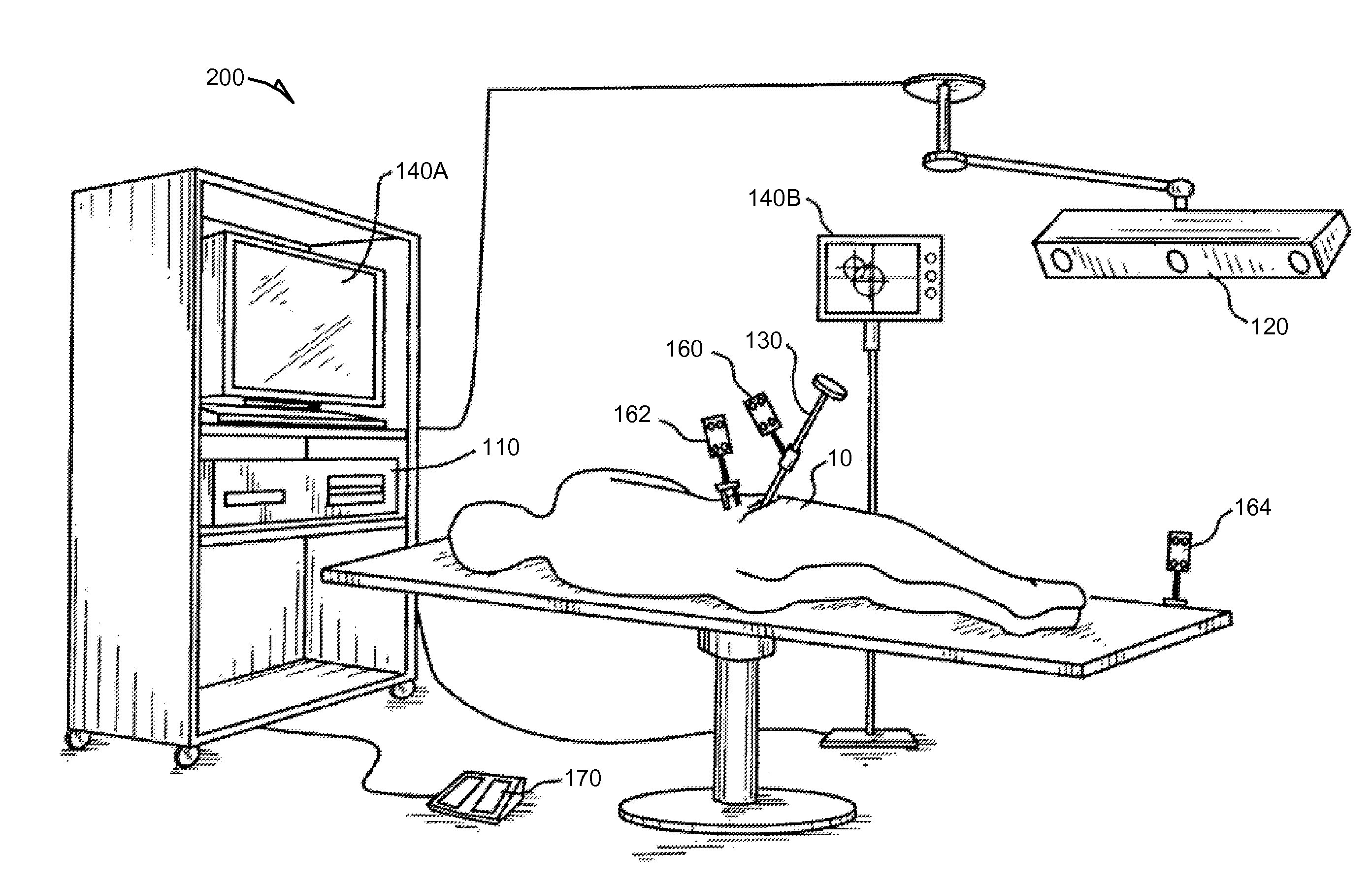
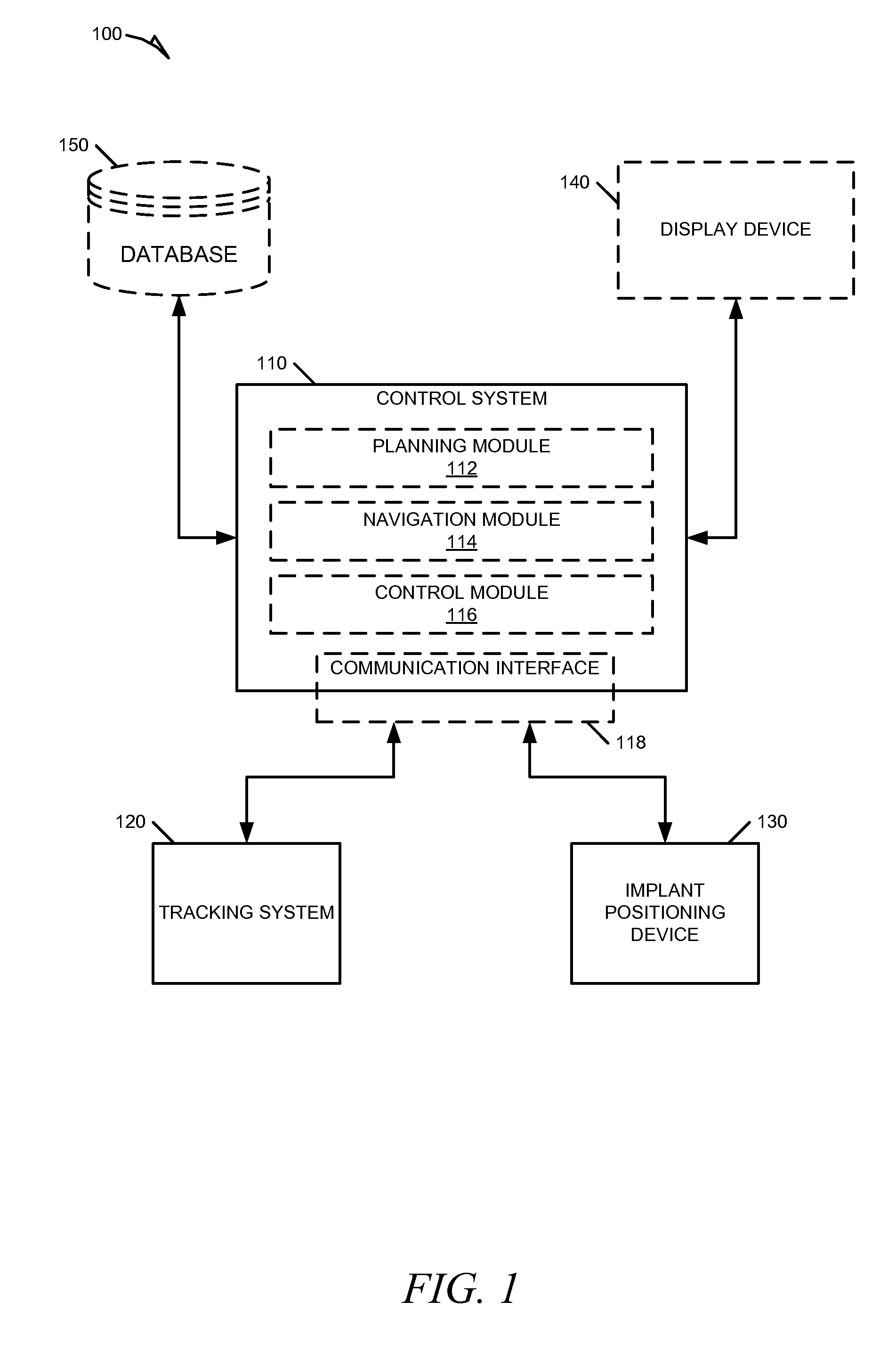
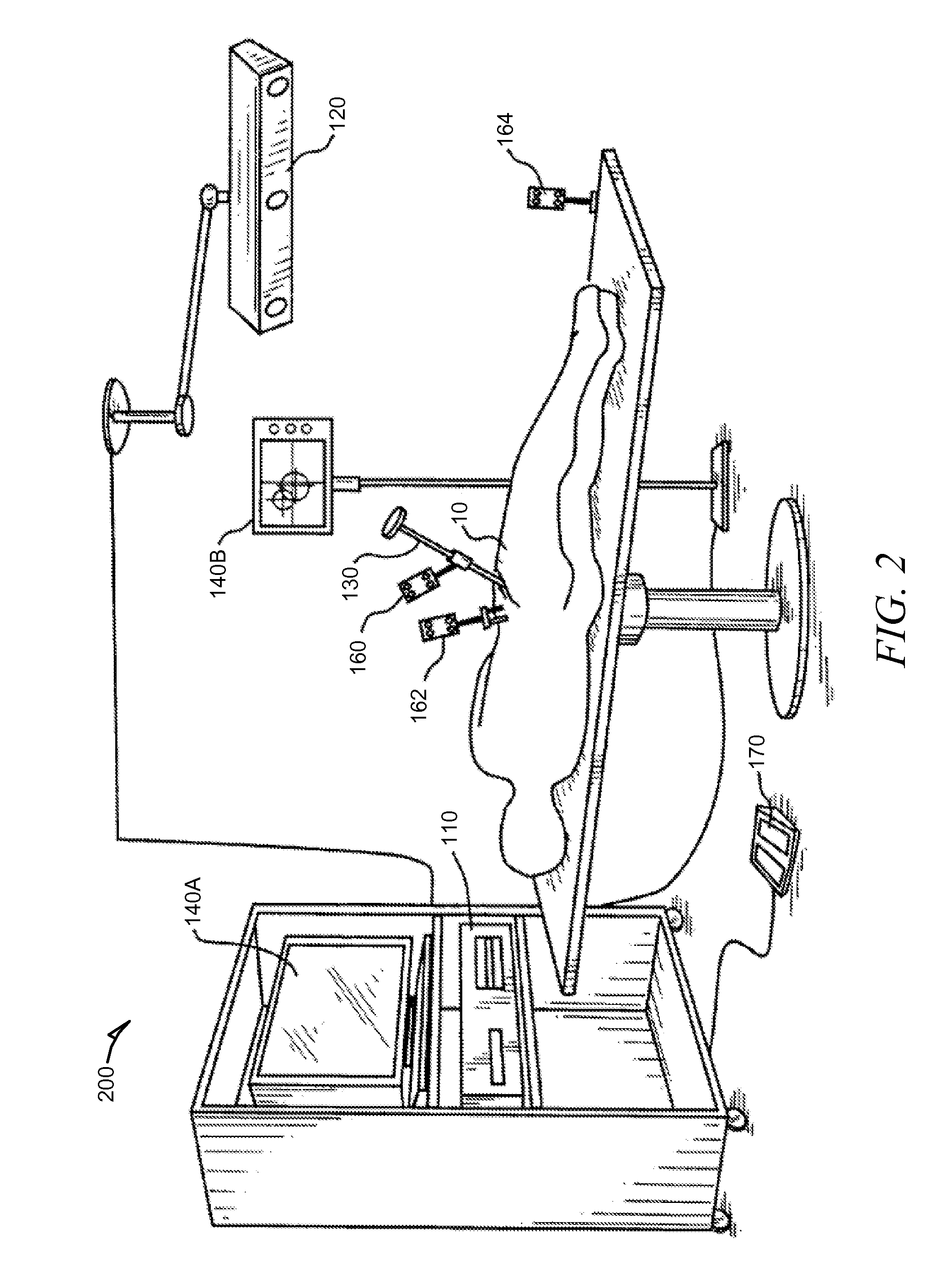
[0035]Example systems and methods for providing and using a navigated and computer controlled implant positioning device are described. In some example embodiments, the systems and methods for computer-aided navigation and control of an implant positioning device can involve a computer-controllable powered impactor. In an example, the computer-controllable powered impactor can be used by a surgeon to insert a prosthetic acetabular cup into the acetabulum of an implant host (e.g., a patient). In other examples, an alternative implant positioning device can be used to assist in a similar arthroplasty procedure, such as a total knee replacement. In the following description, for purposes of explanation, numerous specific details are set forth in order to provide a thorough understanding of example embodiments. It will be evident, however, to one skilled in the art, that the present invention may be practiced without these specific details. It will also be evident that a computer contro...


PUM


Abstract

Systems and methods for navigation and control of an implant positioning device are discussed. For example, a method can include operations for accessing an implant plan, establishing a 3-D coordinate system, receiving tracking information, generating control signals, and sending the control signals to the implant positioning device. The implant plan can include location and orientation data describing an ideal implant location and orientation in reference to an implant host. The 3-D coordinate system can provide spatial orientation for the implant positioning device and the implant host. The tracking information can identify current location and orientation data within the 3-D coordinate system for the implant positioning device and implant host during a procedure. The control signals can control operation of the implant positioning device to assist a surgeon in positioning the implant according to the implant plan.

Description

CROSS-REFERENCE TO RELATED APPLICATION[0001]This application claims the benefit of U.S. Provisional Application No. 61 / 724,601, titled “Systems and Method for Navigation and Control of an Implant Positioning Device,” filed Nov. 9, 2012, which is incorporated herein by reference in its entirety.TECHNICAL FIELD[0002]This application relates generally to semi-active surgical robotics, and more specifically to systems and methods to provide computer-aided navigation and control of an implant positioning device.BACKGROUND[0003]The use of computers, robotics, and imaging to aid orthopedic surgery is well known in the art. There has been a great deal of study and development of computer-aided navigation and robotics systems used to guide surgical procedures. Two general types of semi-active surgical robotics have emerged and have been applied to orthopedic procedures, such as joint arthroplasty. The first type of semi-active robotics attach the surgical tool to a robotic arm that resists m...

Claims


Application Information

Patent Timeline
Patent Type & Authority Applications(United States)
IPC IPC(8): A61B19/00
CPCA61B19/5244A61B19/2203A61F2/4609A61F2002/4627A61F2002/4628A61F2002/4632A61F2002/4681A61F2002/30538A61F2002/4688A61B2034/104A61B2034/2055A61B34/10A61B34/30A61B2034/301A61B34/00A61B2034/2046A61F2/46A61F2/4603A61B34/70A61F2002/4625A61F2002/4633A61B34/20A61B34/32
Inventor NIKOU, CONSTANTINOSJARAMAZ, BRANISLAVMCCANDLESS, BENJAMIN OLIVER
Owner BLUE BELT TECH
Why Eureka
Try Eureka