
Continuously rotatable electronic-device organizer

a technology of electronic devices and organizers, applied in the direction of dismountable cabinets, coupling device connections, furniture parts, etc., can solve the problems of occupying a large workspace area, causing the cable to be strung throughout, and causing the cable to be twisted throughou

Active Publication Date: 2007-11-20
MAYER PETER L
View PDF17 Cites 29 Cited by
  • Summary
  • Abstract
  • Description
  • Claims
  • Application Information

AI Technical Summary

Benefits of technology

"The present invention is a rotatable storage device that allows for easy access to electronic devices such as printers, fax machines, computers, and scanners. The device includes a base member with high and low voltage connectors, a support platform that can rotate, and a rotatable connector that connects to the support platform and the base member. The device also includes a first column and a second platform that can rotate with respect to the first platform. The technical effect of this invention is that it provides a convenient and flexible way to access electronic devices while also allowing for easy rotation and positioning of the support platform."

Problems solved by technology

However, spatially arranging all of these useful devices consumes an inordinate amount of desk-top real-estate, leaving less and less room to actually accomplish the work which the devices are intended to facilitate.
The aggregation of devices on a desk brings with it a multitude of cables strung throughout and consuming further workspace area.
The cables are not only unattractive; they also interfere with the workspace and become a nuisance.
However, storing devices on the floor suffers from the disadvantages of making the devices difficult or inconvenient to reach, easy to damage by kicking, stepping on, or otherwise, and also consuming valuable floor space.

Method used


Image

  • Continuously rotatable electronic-device organizer
  • Continuously rotatable electronic-device organizer
  • Continuously rotatable electronic-device organizer

Examples


Embodiment Construction

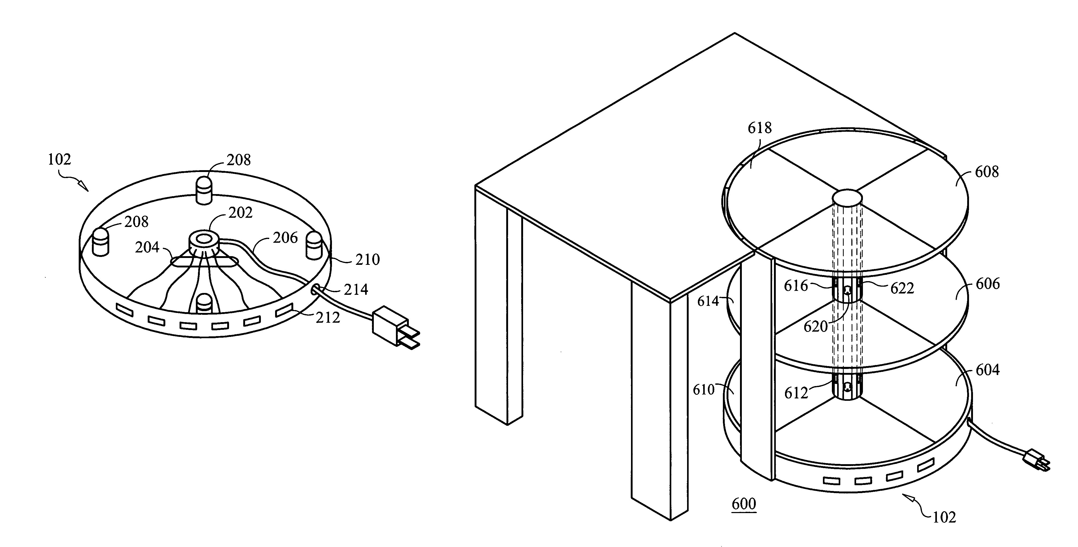
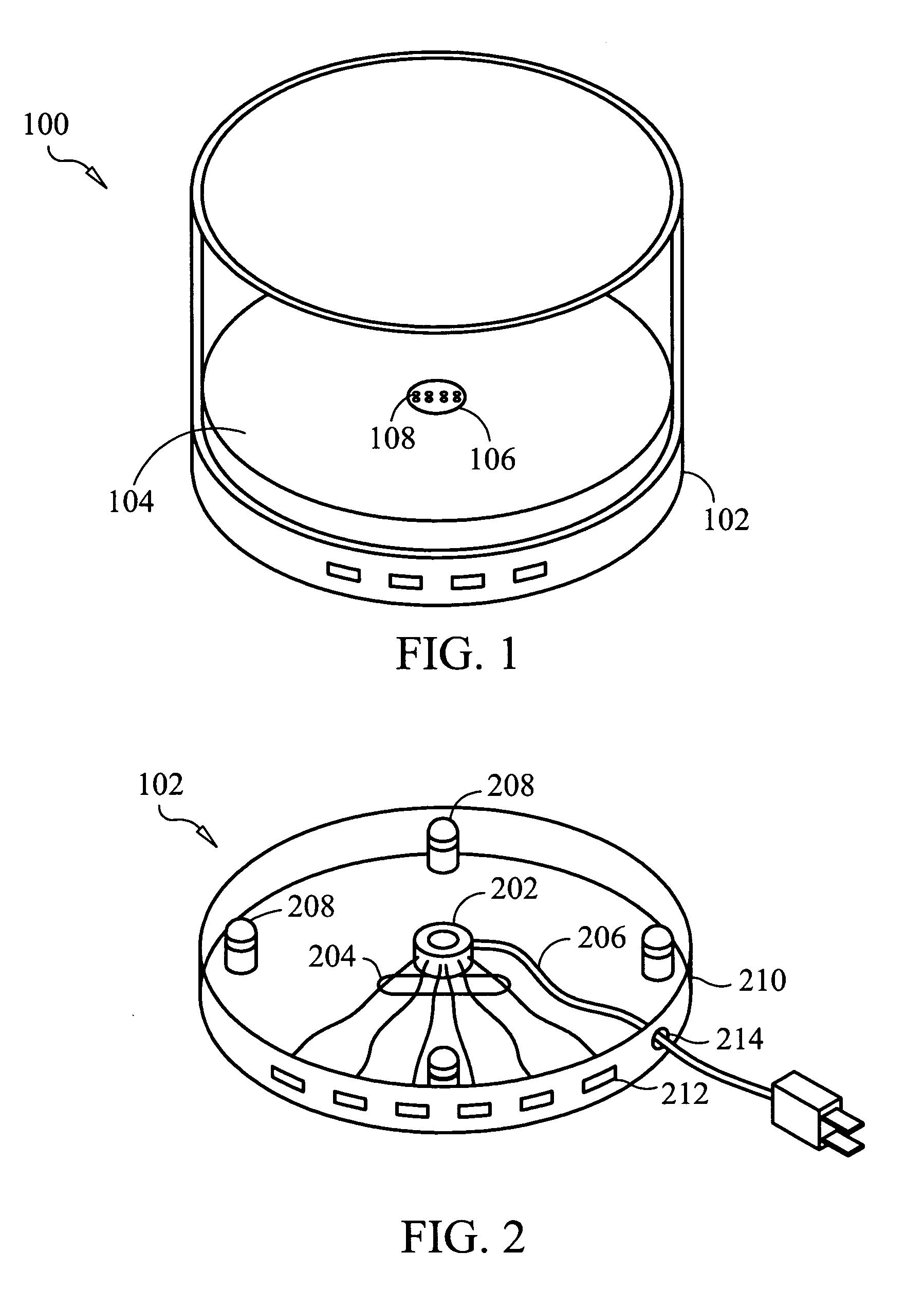
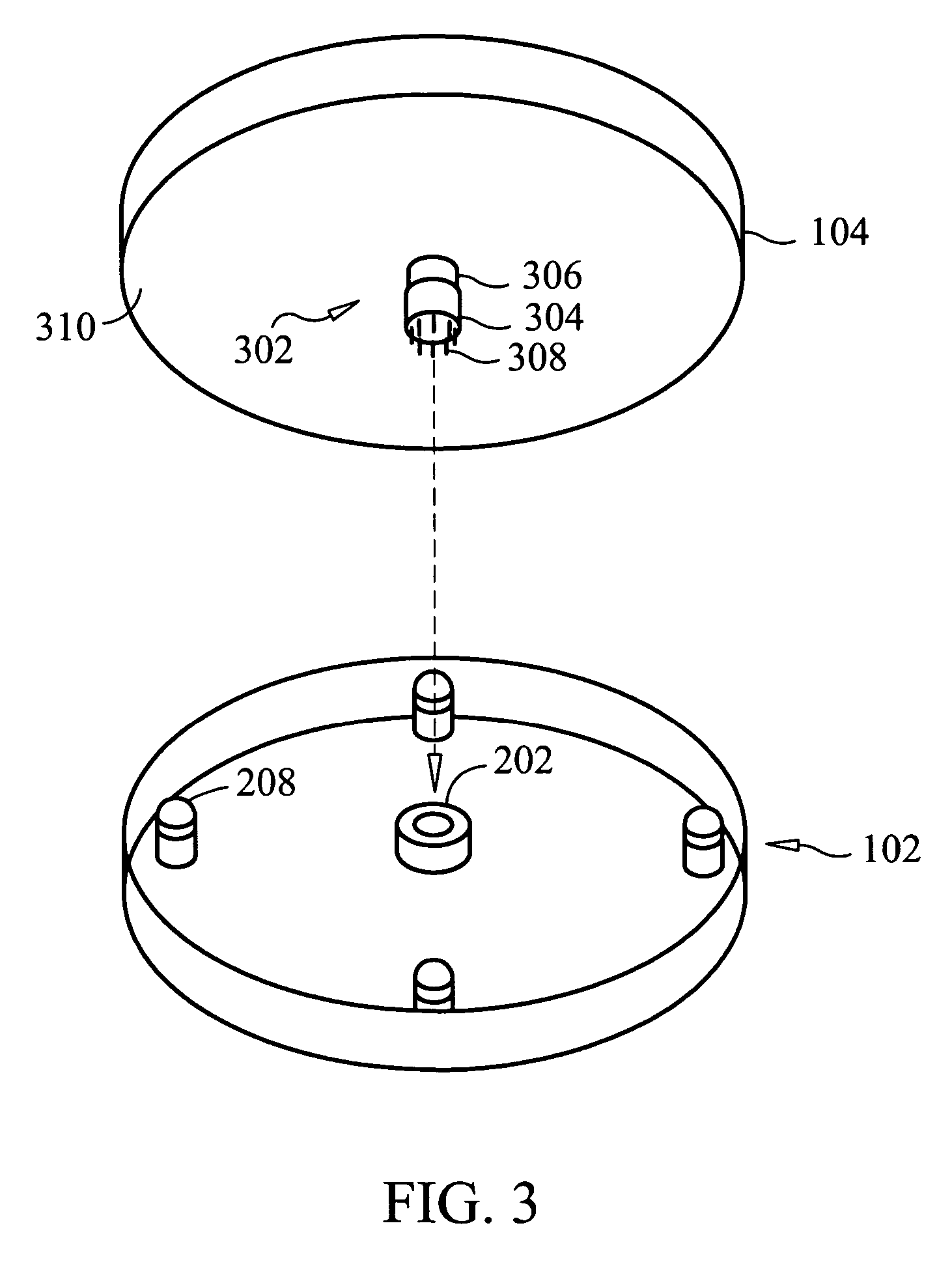
[0019]The present invention provides a rotatable storage device including a rotatable platform configured for storing and allowing ease of access to electronic devices such as, printers, facsimile machines, computers, scanners, and others. The rotatable platform includes high and low voltage receptacle for connection to the electronic devices. The high and low voltage receptacles provide power, as well as data and voice communication to the electronic devices. The receptacles are connected to a rotatable connector allowing the rotatable platform and receptacle to be rotated in unison without the twisting or tangling of the power and connecting wires. The rotatable connector can take the form of sliprings, brushes, mercury rotatable connectors, or other known devices.

[0020]Referring now to the drawing figures in which like reference designators refer to like elements, there is shown in FIG. 1 an assembly 100 of the present invention. The assembly 100 includes a base section 102 and a...


PUM


Abstract

The present invention provides a rotatable storage device including a rotatable platform configured for storing and allowing ease of access to electronic devices such as, printers, facsimile machines, computers, scanners, and others. The rotatable platform include high and low voltage receptacle for connection to the electronic devices. The high and low voltage receptacles provide power, as well as data and voice communication to the electronic devices. The receptacles are connected to a rotatable connector allowing the rotatable platform and receptacle to be rotated in unison without the twisting or tangling of the power and connecting wires. The rotatable connector can take the form of sliprings, brushes, mercury rotatable connectors, or other known devises.

Description

FIELD OF THE INVENTION[0001]The invention relates generally to storing and organizing electronic devices and more specifically to a device that holds and supplies power and data communication to a plurality of common desk-top items while allowing continuous rotatable access to each item.BACKGROUND OF THE INVENTION[0002]Technology has provided us with many useful tools for making communication and basic office functions efficient, easy, and of higher quality. Some of these devices include computers, computer monitors, printers, scanners, facsimile machines, copiers, cordless telephones, transponders for wireless connectivity, paper shredders, surge protectors, and others. However, spatially arranging all of these useful devices consumes an inordinate amount of desk-top real-estate, leaving less and less room to actually accomplish the work which the devices are intended to facilitate.[0003]Additionally, each device must be powered, which requires a separate power-carrying cable runni...

Claims


Application Information

Patent Timeline
Patent Type & Authority Patents(United States)
IPC IPC(8): A47B91/00
CPCH01R25/006Y10S248/918H01R35/02
Inventor MAYER, PETER L.
Owner MAYER PETER L
Learn More