Lancing apparatus

a technology of lancing apparatus and fingertip, which is applied in the field of lancing apparatus, can solve the problems of fingertip bleeds easily, fingertip bleeds relatively easily, and fingertip lancing involves relatively strong pain, and achieves stable lancing operation.

Inactive Publication Date: 2007-11-20
ARKRAY INC
View PDF26 Cites 110 Cited by
  • Summary
  • Abstract
  • Description
  • Claims
  • Application Information

AI Technical Summary

Benefits of technology

[0009]An object of the present invention is to provide a lancing apparatus which enables any user to properly extract blood from a selected portion without putting excessive financial burden on the user. Another object of the present invention is to provide a lancing apparatus which prevents the user from forgetting to perform the lancing depth adjustment and which is advantageous in terms of cost.

Problems solved by technology

Although, the fingertip bleeds easily, lancing of the fingertip involves relatively strong pain.
Further, the tendency to bleed from the skin varies among individuals at any portion of the skin.
However, when the same front cover is used for the blood extraction from the fingertip and that from the forearm, proper blood extraction may not be performed in the following reasons.
Therefore, the positional relationship between the needle of the lancet and the skin, and hence, the lancing depth differ among individuals, which hinders stable lancing operation.
Further, when a lancing apparatus having a manual suction mechanism is used, the positional relationship between the lancing apparatus and the skin is likely to deviate due to the vibration of the lancing apparatus during the suction.
Such preparation and use of a plurality of lancing apparatuses is inconvenient for the user and puts the financial burden on the user.
However, with a single kind of lancing apparatus, proper blood extraction is possible only from a single particular portion, which is inconvenient.
Such a large number of parts leads to an increase in the manufacturing cost.
In such a case, an excessive or insufficient amount of blood may be extracted or the user may suffer discomfort.

Method used


Image

  • Lancing apparatus
  • Lancing apparatus
  • Lancing apparatus

Examples


Embodiment Construction

[0074]Preferred embodiments of the present invention will be described below in detail with reference to the accompanying drawings.

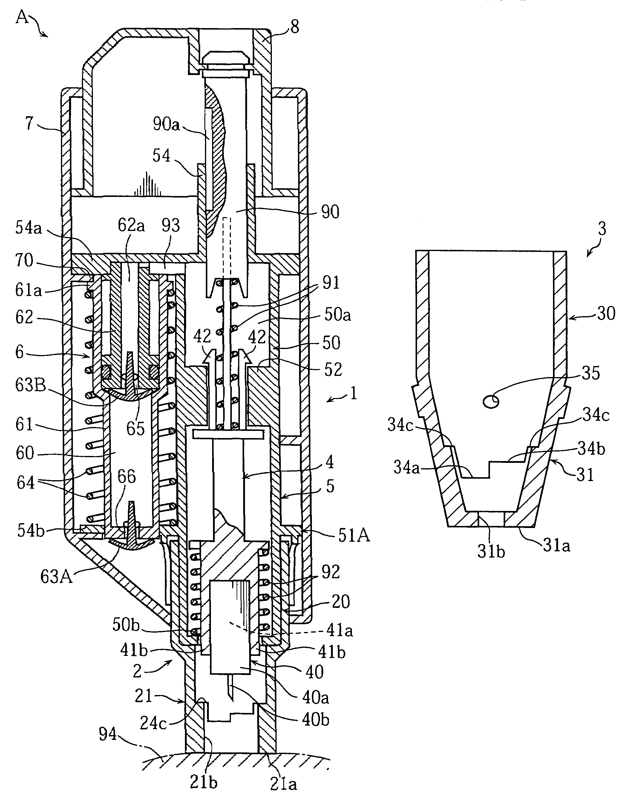
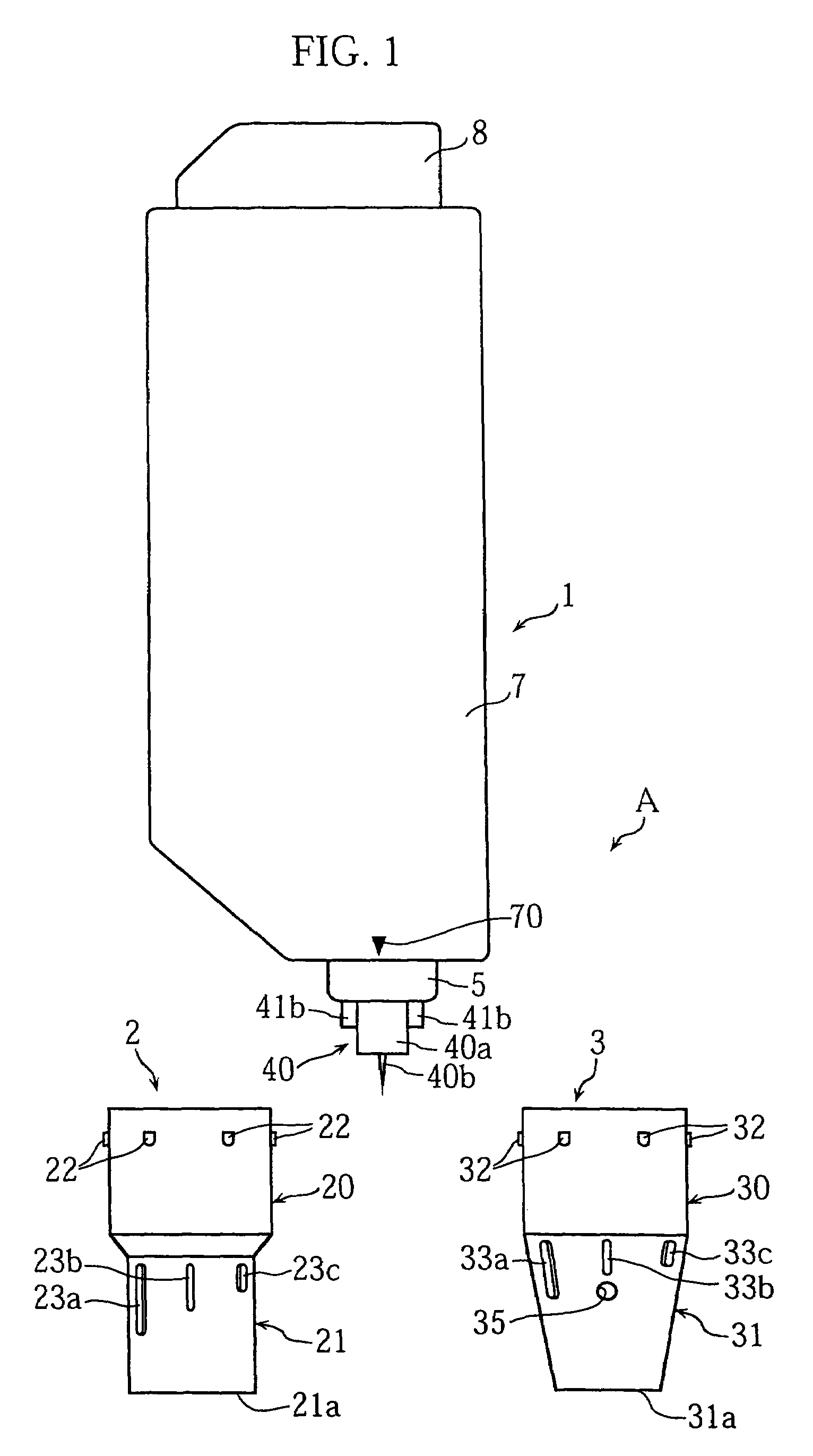
[0075]As shown in FIG. 1, the lancing apparatus A in this embodiment includes an apparatus body 1, a lancet 40, a first front end cover 2 and a second front end cover 3. The lancet 40 includes a main body 40a and a needle 40b projecting from the main body. The main body 40a may be made of a synthetic resin, for example. The needle 40b may be made of metal and integrally formed on the main body 40a by insert molding, for example.

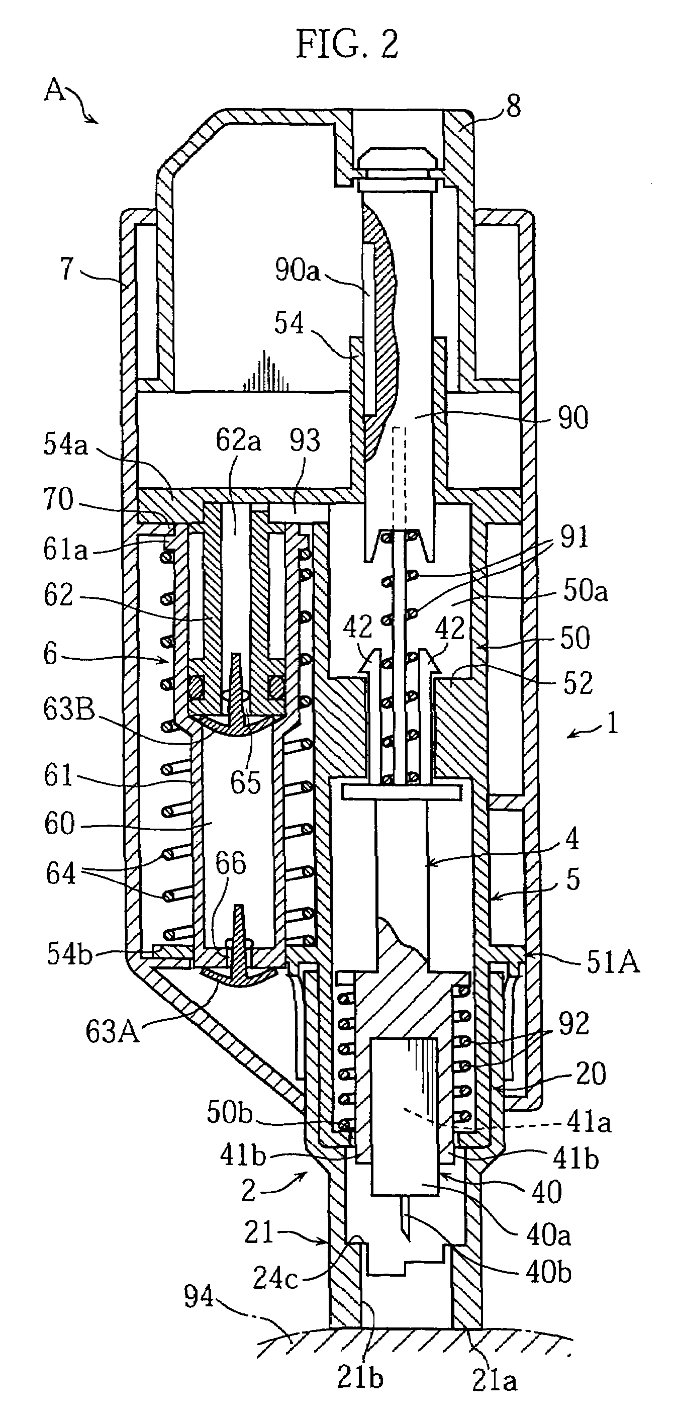
[0076]The first front end cover 2 has a structure for enabling proper blood extraction from a forearm, whereas the second front cover 3 has a structure for enabling proper blood extraction from a fingertip. Thus, the one which is suitable for the portion to be lanced is selected from the front end covers 2 and 3 and attached to the lancing apparatus body 1. FIG. 2 illustrates the state in which the first front end cover 2 is attac...


PUM


Abstract

The present invention relates to a lancing apparatus (A) comprising an apparatus body (1) including a housing (5) and a movable member for advancing a needle (40b), the movable member being arranged movably in the housing (5), and a plurality of front end covers (2, 3) each for coming into contact with a portion to be lanced in lancing. Preferably, the plurality of front end covers (2, 3) have different structures adapted for lancing different portions and are removably attachable to a same portion of the apparatus body (1) individually. A suitable cover (2 or 3) for the portion to be lanced is selectable from the front end covers (2, 3), and the selected front end cover (2 or 3) is attached to the apparatus body (1) in use.

Description

TECHNICAL FIELD[0001]The present invention relates to a lancing apparatus used to stick a tip end of a lancet into skin for extracting blood, other body fluid or tissue for testing.BACKGROUND ART[0002]In a typical lancing apparatus, a lancet holder holding a lancet is accommodated in a housing to which a front end cover is attached. When a predetermined operation is performed, the lancet holder advances toward the front end of the front end cover by a spring force. Since the lancet is generally disposable, the front end cover is made removable so that it can be removed in attaching or detaching the lancet. In using the lancing apparatus, the front end cover is pressed against skin of the human body. The front end cover is formed with an opening for allowing the needle to lance the skin. When the lancet holder is advanced, the lancet passes through the opening to lance the skin.[0003]For example, blood is extracted from the fingertip or the forearm. Although, the fingertip bleeds eas...

Claims


Application Information

Patent Timeline
Patent Type & Authority Patents(United States)
IPC IPC(8): A61B17/32A61B5/15
CPCA61B5/1411A61B5/150022A61B5/150099A61B5/15019A61B5/150213A61B5/150221A61B5/150412A61B5/150503A61B5/15113A61B5/15117A61B5/1519A61B5/15194
Inventor FUKUZAWA, MASAHIROKOIKE, MASUFUMIUCHIGAKI, TAKATOSHI
Owner ARKRAY INC
Why Eureka
Try Eureka