Wet electrostatic precipitator for treating oxidized biomass effluent

a technology of biomass effluent and wet electrostatic precipitator, which is applied in the direction of material analysis, separation processes, instruments, etc., can solve the problems of increasing installation and operation cost and complexity

Active Publication Date: 2007-11-20
ZENVIRO TECH HLDG INC
View PDF56 Cites 32 Cited by
  • Summary
  • Abstract
  • Description
  • Claims
  • Application Information

AI Technical Summary

Problems solved by technology

These semi-organic particles have traditionally precipitated on collecting surfaces in dry precipitators forming potential fire and maintenance hazards.
These three separate pieces of equipment have various physical interconnections and multiple control connections that increase the cost and complexity of installation and operation.

Method used


Image

  • Wet electrostatic precipitator for treating oxidized biomass effluent
  • Wet electrostatic precipitator for treating oxidized biomass effluent
  • Wet electrostatic precipitator for treating oxidized biomass effluent

Examples


Embodiment Construction

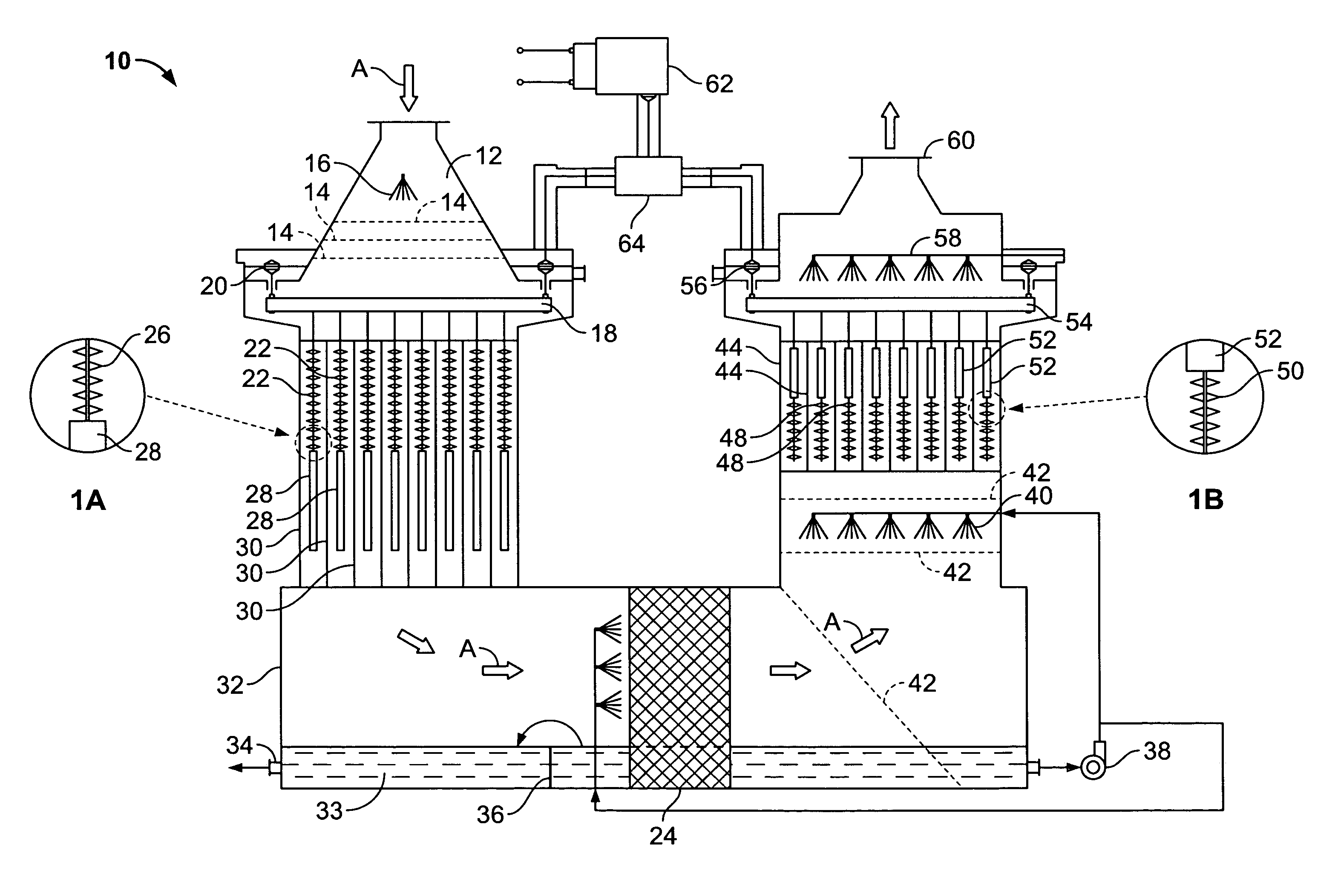
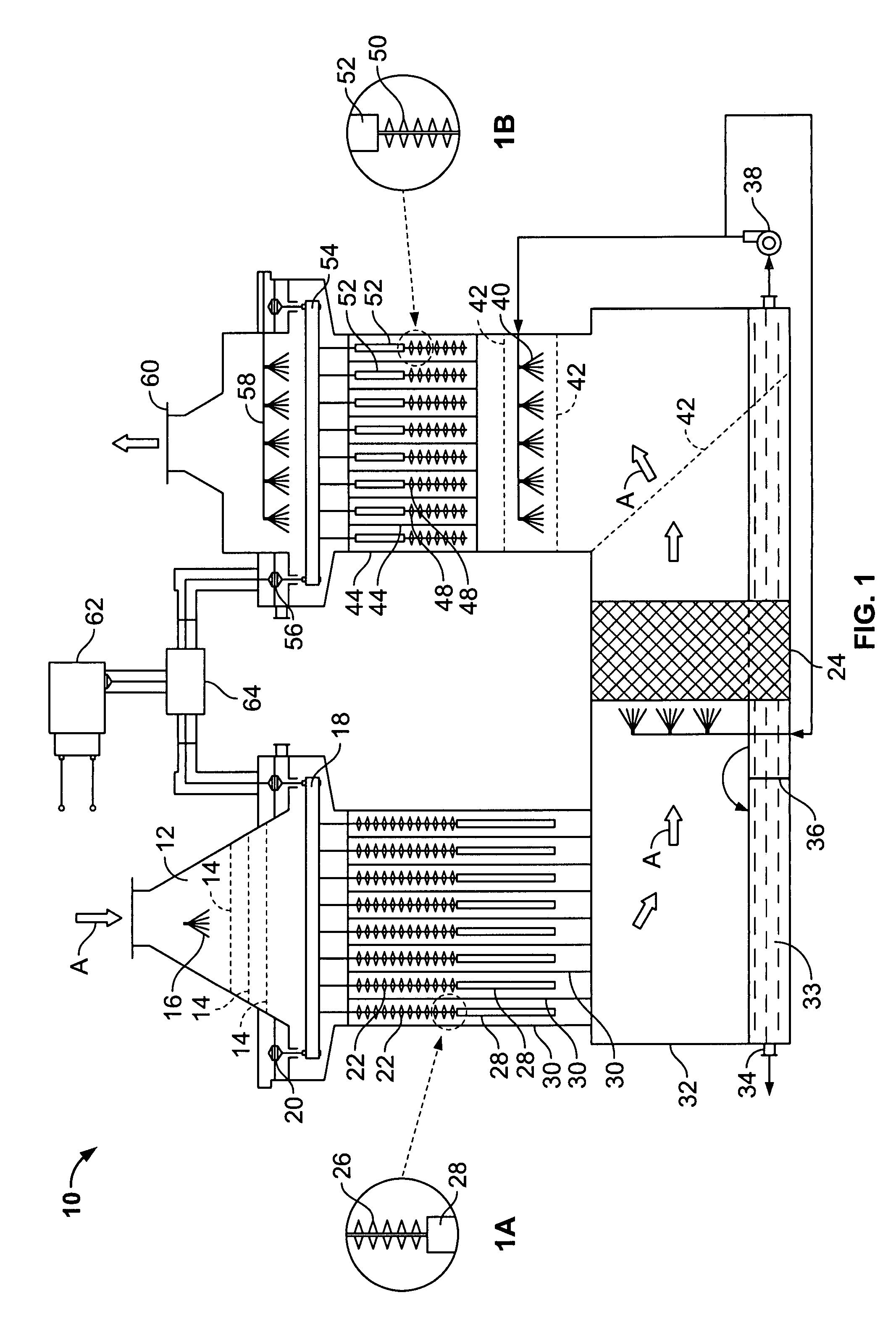
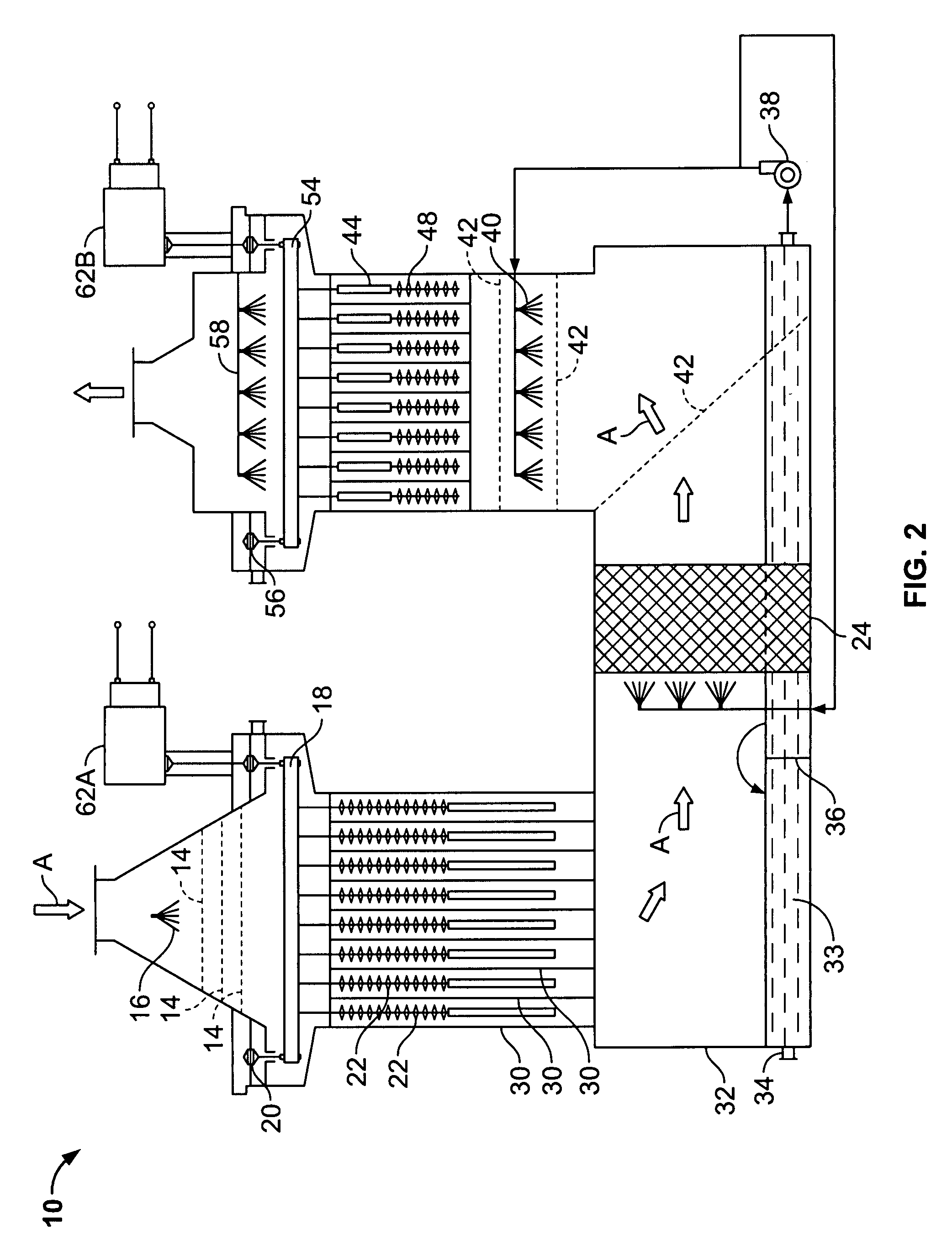
[0015]The invention, as shown in FIG. 1, involves an apparatus 10 comprised of an inlet transition 12 that includes a gas distribution perforated plate 14 and a fine liquid mist nozzle 16 located downstream of, and proximal to the inlet 12. A support structure 18 for ionizing electrodes is positioned downstream of the distribution plate 14. Support insulators 20 isolate negative ionizing electrodes from positive tubes while ionizing electrodes 22, having a charging stage with sharp corona generating points 26 and a smooth repelling stage 28, as shown in FIG. 1A, extend from the support structure 18.

[0016]The ionizing electrodes 22 are preferably located centrally in the spaces defined by collecting surfaces 30 (“collectors”). These collecting surfaces 30 can be created by tubular or flat plate structures. Located below the collectors 30, and preferably in the bottom of a housing 32 is a sump for the down-flow section for collecting liquid. A drain nozzle 34 is also located in the vi...


PUM

PropertyMeasurementUnit
sizeaaaaaaaaaa
sizeaaaaaaaaaa
sizeaaaaaaaaaa

Abstract

An apparatus for removing particulate matter from a biomass combustion gas stream, the apparatus having a mist-producing element that mixes a gas stream entering the apparatus with liquid droplets; a Wet Electrostatic Precipitator (WESP) section that includes ionizing electrodes that electrically charge the particulate matter and the intermixed liquid droplets and collecting surfaces under the influence of an electrical field which attract and remove electrically-charged particulate matter and intermixed liquid droplets from the gas stream; and a scrubbing section that provides for additional scrubbing of the gas.

Description

CROSS-REFERENCE TO RELATED PATENT APPLICATIONS[0001]This patent application is a continuation-in-part of copending U.S. patent application Ser. No. 11 / 366,274, filed Mar. 2, 2006 entitled Dual Flow Wet Electrostatic Precipitator that claims the benefit of U.S. Provisional Patent Application No. 60 / 657,901 filed Mar. 2, 2005.FIELD OF THE INVENTION[0002]This invention pertains to a Wet Electrostatic Precipitator (WESP) apparatus and method for removing particulate matter and environmentally hazardous gases produced from the combustion of biomass and biomass supplemented fuel sources. The invention also pertains to an apparatus having the capacity to continuously self-clean collected biomass derived particulate matter, while also scrubbing acid gases derived from biomass oxidation, and act as an electrode ozone generator or alternatively as a non-thermal plasma generator for biomass derived nitrous oxidation conversion in a single unitary device.BACKGROUND OF THE INVENTION[0003]There h...

Claims


Application Information

Patent Timeline
Patent Type & Authority Patents(United States)
IPC IPC(8): B03C3/014
CPCB01D47/06B01D47/14B03C3/06B03C3/16B03C3/025B03C2201/10
Inventor RAY, ISAACWEST, MARK A.ALTSHULER, BORISGINGER, BRADLEY L.
Owner ZENVIRO TECH HLDG INC
Why Eureka
Try Eureka