Inorganic scintillator, and radiation detector and PET apparatus employing it

a scintillator and inorganic technology, applied in the direction of instruments, conversion screens, nuclear engineering, etc., to achieve the effects of short decay time, short decay time, and high light outpu

Active Publication Date: 2007-11-20
OXIDE
View PDF7 Cites 22 Cited by
  • Summary
  • Abstract
  • Description
  • Claims
  • Application Information

AI Technical Summary

Benefits of technology

[0011]The scintillators mounted in PET apparatuses must exhibit high light output and a short decay time, as essential optical characteristics. In particular, scintillators with short decay times are desired from the viewpoint of shortening examination times and relieving the burden on patients being examined by PET, as well as from the viewpoint of preventing “pile-up” of multiple fluorescent pulses to obtain a radiation detector with high time resolution. However, the oxide fluorescent material described in Japanese Patent Publication Laid-open No. 2001-4753 has a long decay time and is therefore in need of improvement for mounting in a PET apparatus.
[0012]It is therefore an object of the present invention, which has been accomplished in light of the circumstances described above, to provide an inorganic scintillator having a high light output and a light intensity peak wavelength in the wavelength range of 450-600 nm, which is the region of high photodiode conversion efficiency, as well as a radiation detector and PET apparatus employing the inorganic scintillator.
[0017]The scintillator of the invention is also preferably in a single crystal form. A single crystal form will allow the superior scintillator properties to be more reliably exhibited.
[0019]A value of x, representing the Ce content, that satisfies the above inequality (6) will increase the number of oxygen-hexacoordinated Ce atoms. This can result in a longer peak wavelength for the intensity spectrum of fluorescence outputted upon incidence of radiation. The peak wavelength can therefore be more reliably adjusted to the range of 450 nm to 600 nm.
[0025]A PET apparatus of the invention is provided with the radiation detector of the invention described above. In the PET apparatus of the invention, the intensity spectrum wavelength of fluorescence emitted from the inorganic scintillator of the invention is between 450 nm and 600 nm. Thus, fluorescence will be converted to an electrical signal by the photodiode with high conversion efficiency. Radiation is therefore detected at high precision. Moreover, a photodiode is used as the element for conversion of the fluorescence emitted from the inorganic scintillator into an electrical signal. Since a photodiode can be used even in the presence of a powerful magnetic field, an MRI apparatus may be combined with a PET apparatus according to the invention to construct a PET-MRI apparatus. Thus, it is possible to accomplish simultaneous collection of metabolic function information by PET imaging and anatomical position information by MRI imaging, to permit diagnosis based on combination of both images.
[0026]According to the invention, it is possible to provide an inorganic scintillator having a high light output and a light intensity peak wavelength in the wavelength range of 450-600 nm, which is the region of high photodiode conversion efficiency, as well as a radiation detector and PET apparatus employing the inorganic scintillator.

Problems solved by technology

However, the oxide fluorescent material described in Japanese Patent Publication Laid-open No. 2001-4753 has a long decay time and is therefore in need of improvement for mounting in a PET apparatus.

Method used


Image

  • Inorganic scintillator, and radiation detector and PET apparatus employing it
  • Inorganic scintillator, and radiation detector and PET apparatus employing it
  • Inorganic scintillator, and radiation detector and PET apparatus employing it

Examples


example 1

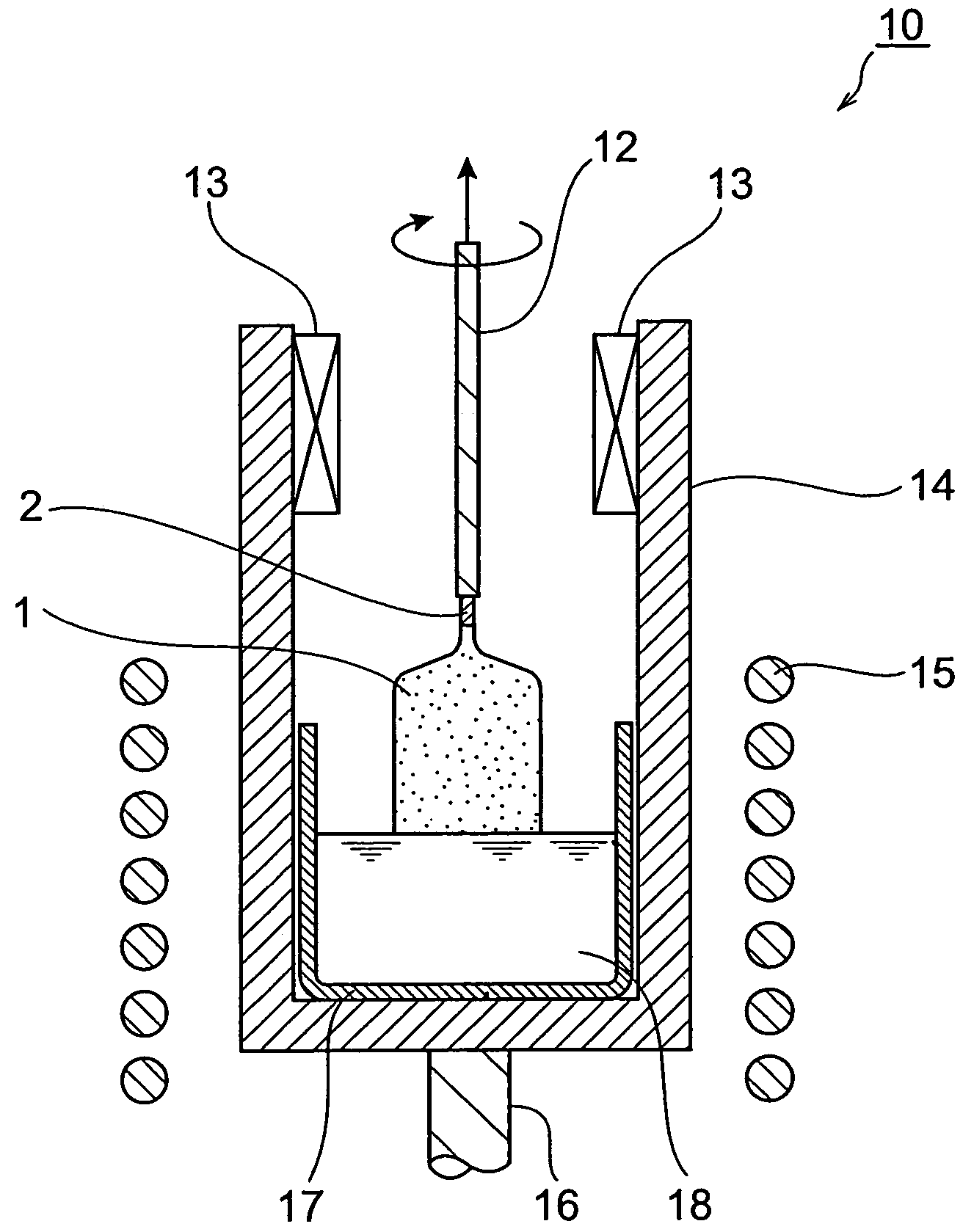
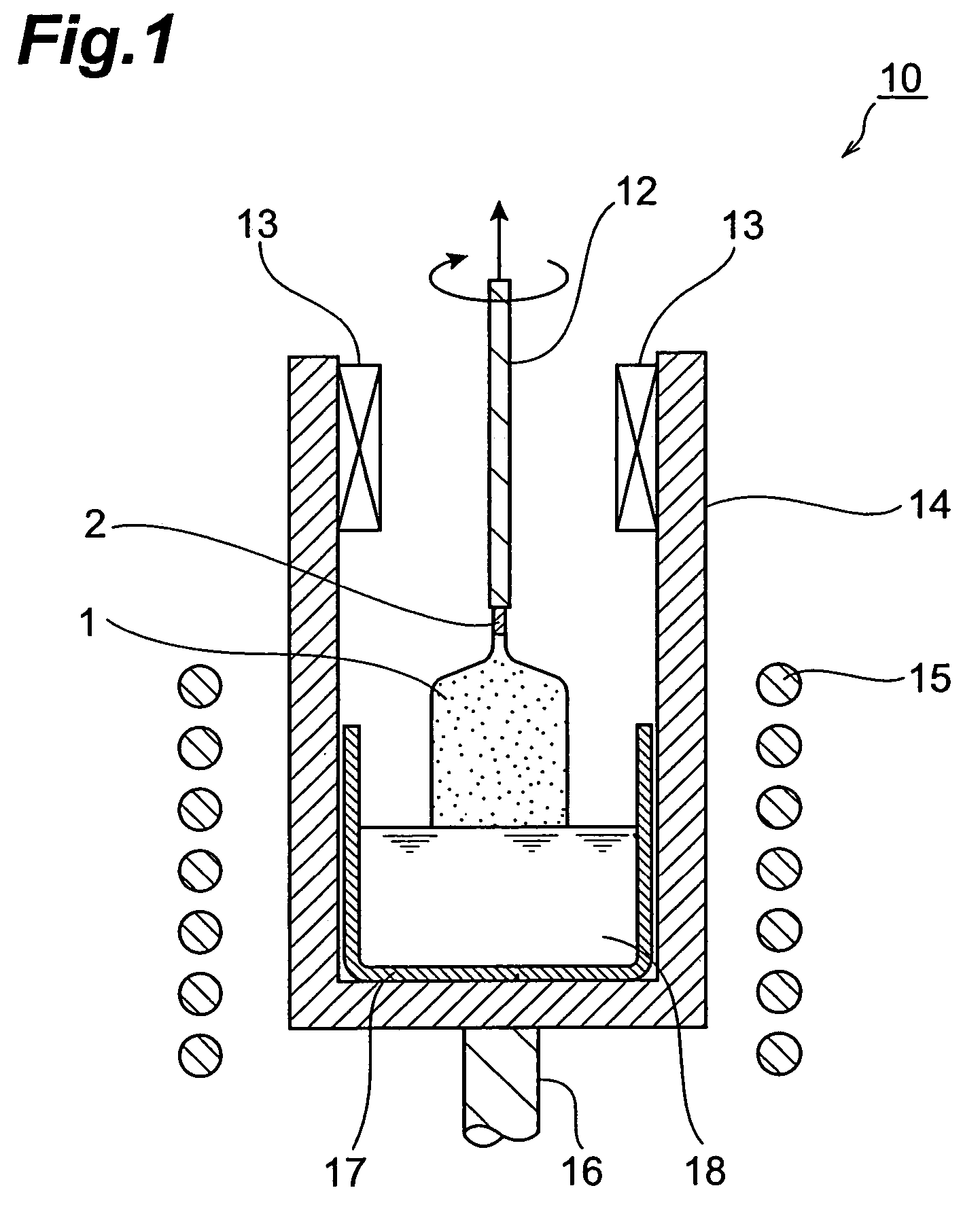
[0058]In an Ir crucible having the same shape shown in FIG. 1 with a diameter of 110 mm, a height of 100 mm and a thickness of 2.5 mm there were loaded 3600.64 g of gadolinium oxide (Gd2O3, 99.99 wt % purity), 1000.64 g of lutetium oxide (Lu2O3, 99.99 wt % purity), 755.44 g of silicon dioxide (SiO2, 99.99 wt % purity) and 43.28 g of cerium oxide (CeO2, 99.99 wt % purity) as the starting materials, and 5400.00 g of the mixture was obtained. The crucible was then placed at a prescribed position of a high-frequency induction heating furnace and the mixture was heated to melting at 1950° C. or higher to obtain a melt (chemical composition of melt: Ce0.02Lu0.4Gd1.58SiO5).

[0059]Next, the end of the lifting rod to which the seed crystal was anchored was placed in the melt for crystal growth. The seed crystal used was a cut-out single crystal composed of a metal oxide containing Lu, Gd, Ce and Si, obtained by an ordinary crystal growth method. The crystal structure of the seed crystal was c...


PUM


Abstract

The inorganic scintillator of the invention has the chemical composition represented by CexLnySizOu (where Ln represents at least two elements selected from among Y, Gd and Lu. 0.001≦x≦0.1, 1.9≦y≦2.1, 0.9≦z≦1.1, 4.9≦u≦5.1) and emits fluorescence upon incidence of radiation, wherein the maximum peak wavelength in the intensity spectrum of the emitted fluorescence is a peak in the range between 450 nm and 600 nm.

Description

BACKGROUND OF THE INVENTION[0001]1. Field of the Invention[0002]The present invention relates to an inorganic scintillator, and to a radiation detector and PET apparatus employing it.[0003]2. Related Background Art[0004]In Positron Emission computed Tomography (hereinafter, PET) apparatuses, the optical characteristics (wavelength conversion properties, etc.) of the scintillators mounted therein have a major influence on the overall apparatus imaging performance. Thus, improvement in the optical characteristics of the scintillator component is one of the most import aspects for enhancing overall apparatus imaging performance. Researchers are therefore actively exploring scintillator materials which can be used to construct scintillators with excellent optical characteristics, and are developing manufacturing techniques such as crystal growth techniques for realizing such scintillators.[0005]PET examination can provide highly detailed information for cancer detection, and its clinica...

Claims


Application Information

Patent Timeline
Patent Type & Authority Patents(United States)
IPC IPC(8): G01T1/20
CPCC09K11/7774G21K4/00G21K2004/06C09K11/77742
Inventor KURASHIGE, KAZUHISAISHIBASHI, HIROYUKIUSUI, TATSUYASHIMIZU, SHIGENORISHIMURA, NAOAKI
Owner OXIDE
Why Eureka
Try Eureka