Data storage device chassis, case and clamp mechanism

a data storage device and clamping mechanism technology, applied in the direction of casings/cabinets/drawers, casings/cabinets/drawers, instruments, etc., can solve the problems of increasing the parts count, increasing the labor cost of gluing or other fixing of plastic strips, and loosening and even separating, so as to reduce vibration

Inactive Publication Date: 2007-11-20
XYRATEX TECH LTD
View PDF4 Cites 32 Cited by
  • Summary
  • Abstract
  • Description
  • Claims
  • Application Information

AI Technical Summary

Benefits of technology

[0028]The use of bevelled cam surfaces causes the data storage device case to be drawn closely into and clamped strongly against the adjacent wall of the data storage device chassis. This gives the effect of an interference fit in the clamped position, whereas sliding in and out of the data storage device can be an easy, almost loose fit. The strong clamp load that can be applied serves to minimise vibrations that may arise during operation of the data storage device.

Problems solved by technology

A number of difficulties arise in the design of a chassis of this type, particularly when trying to accommodate a greater number of data storage devices in a standard volume as space is at a premium and thin chassis walls are therefore required.
Practical problems with this approach include the fact that the plastics strips are often not glued or otherwise fixed in the correct place and that they may become loose and even detached after repeated sliding in and out of the data storage devices.
The use of discrete plastics strips also increases the parts count and the gluing or other fixing of the plastics strips adds significantly to the labour costs.

Method used


Image

  • Data storage device chassis, case and clamp mechanism
  • Data storage device chassis, case and clamp mechanism
  • Data storage device chassis, case and clamp mechanism

Examples


Embodiment Construction

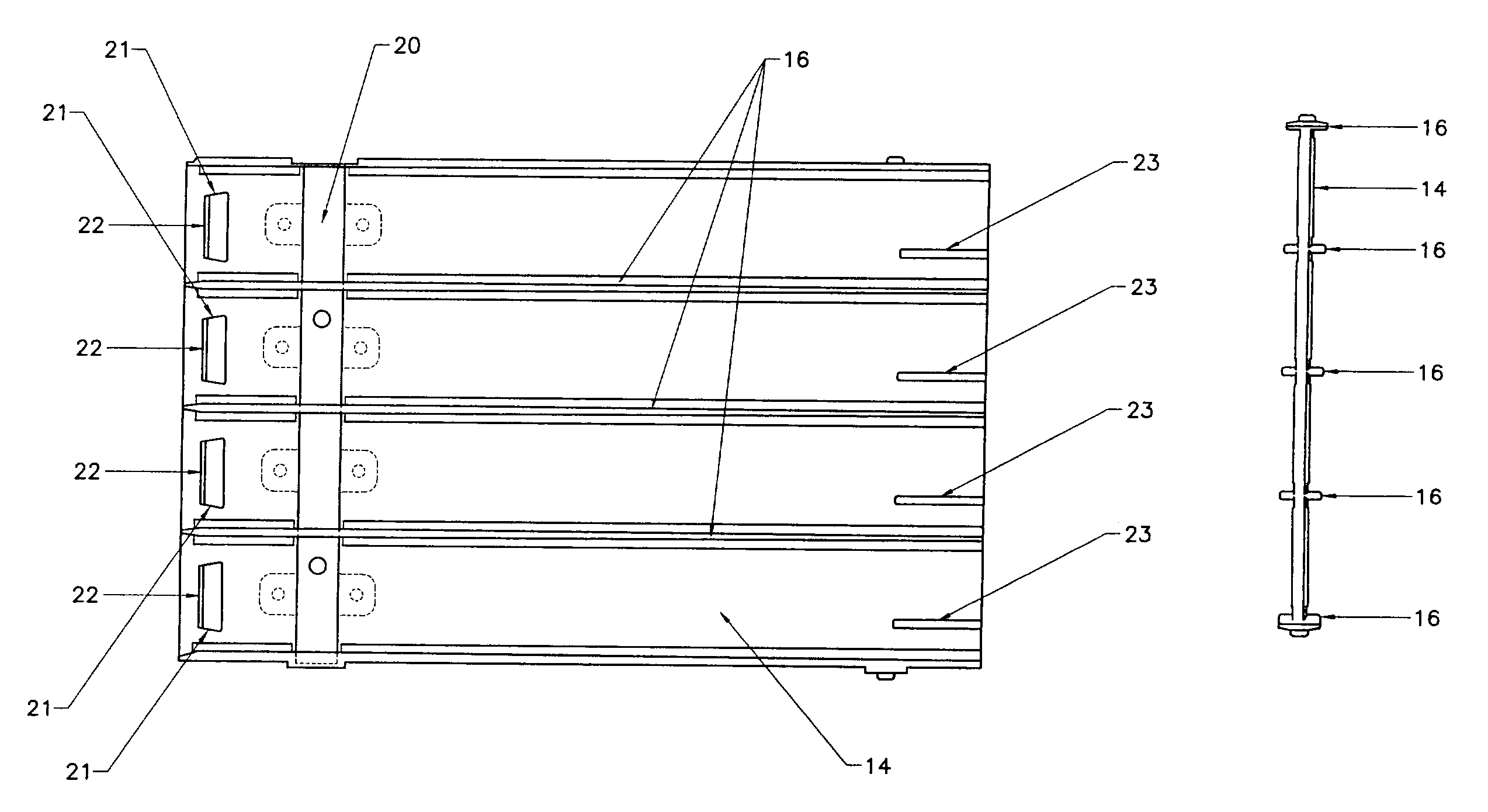
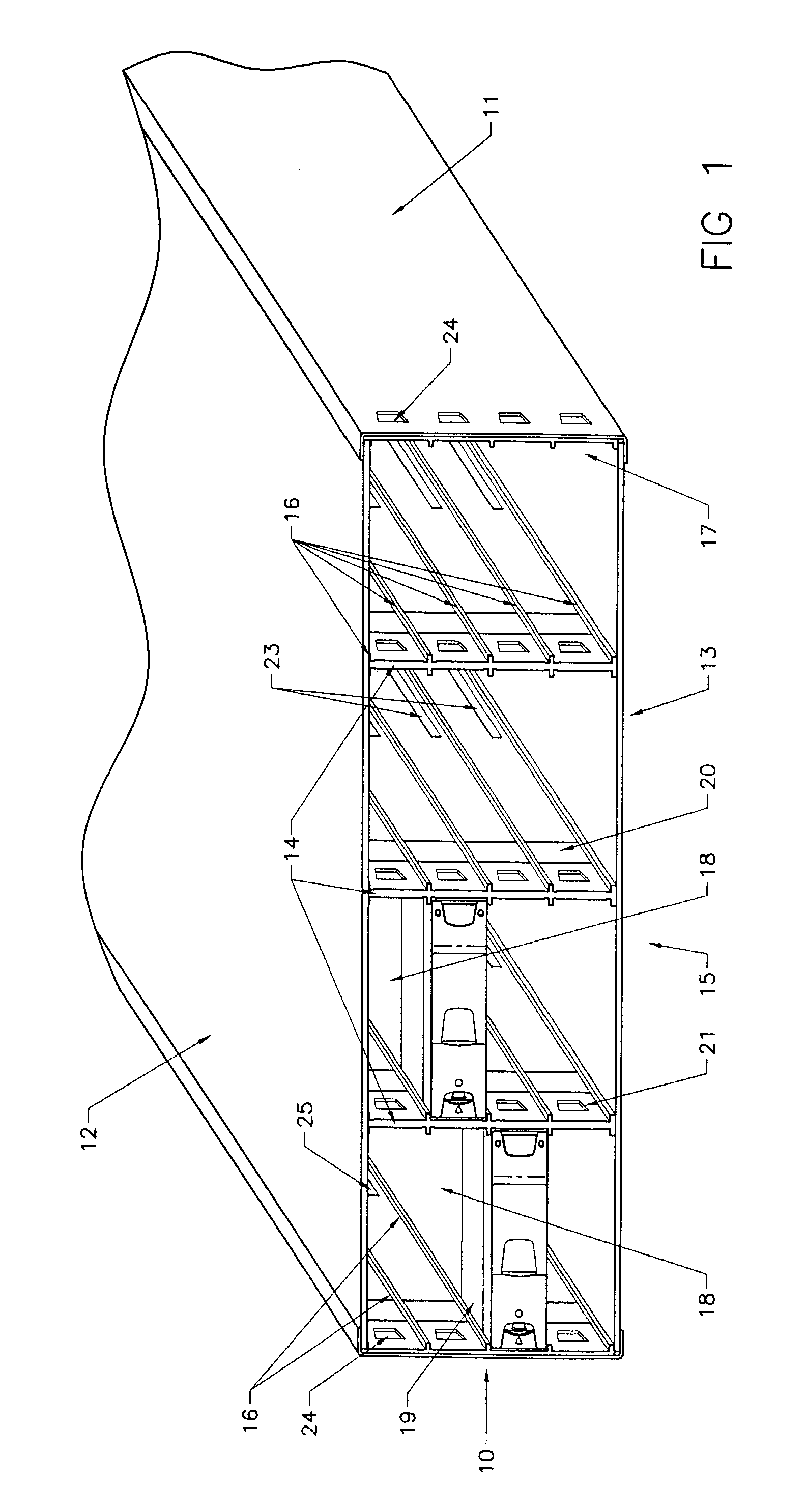
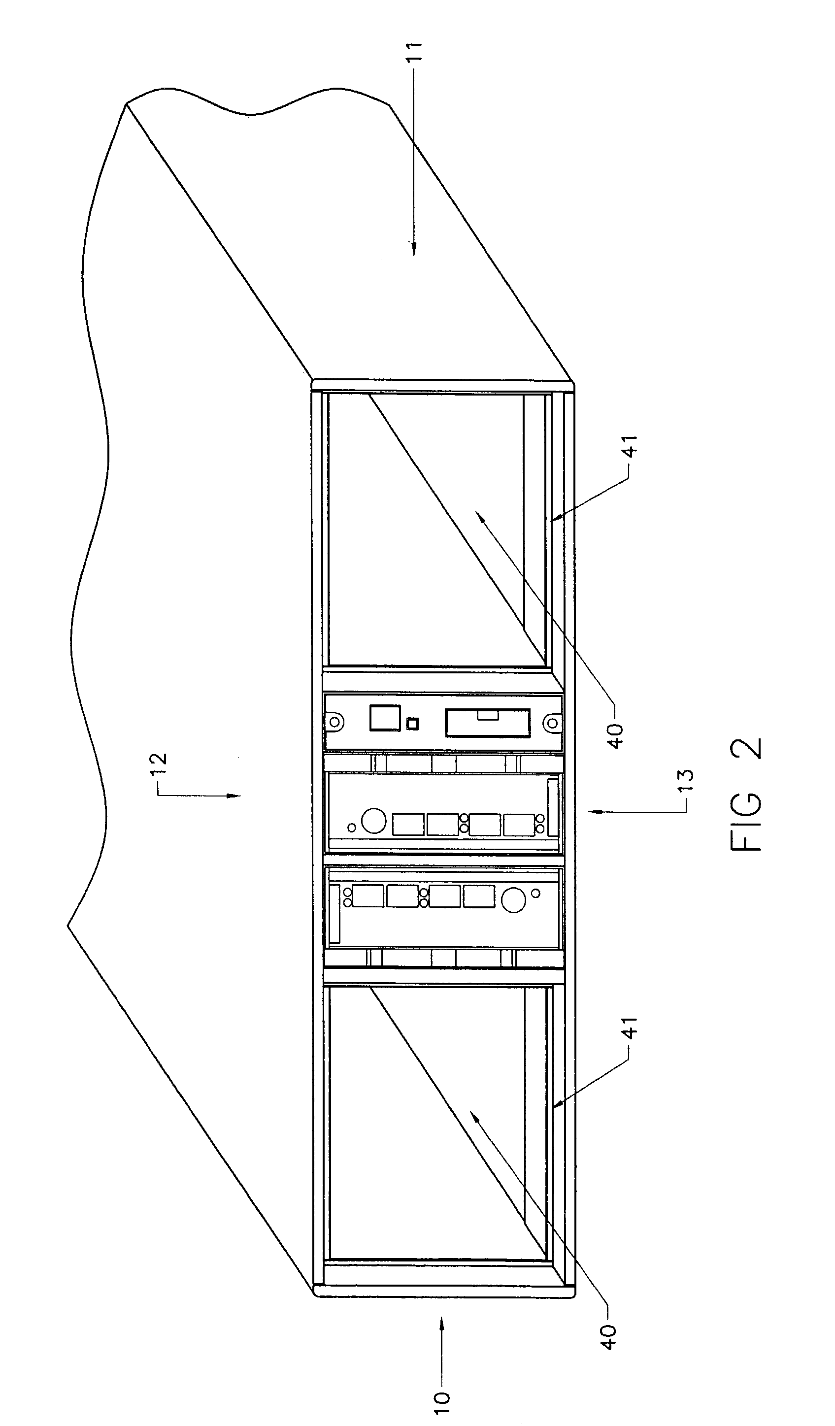
[0045]Referring initially to FIGS. 1 and 2, a generally box-like data storage device chassis 10 has side walls 11, a top wall 12 and a bottom wall 13. Three vertical mid walls 14 pass from the front 15 to approximately the mid point of the chassis 10. Each mid-wall 14 has on each side five guide strips 16 and the inner most facing surfaces of the side walls 11 have similar guide strips 16 which together in this example define a regular array of 4×4 bays 17. Each bay 17 can receive a data storage device 18 which can be slid into and out of the base 17 through the open front 15 of the chassis 11, the guide strips 16 providing the surface along which the cases 19 of the data storage devices 18 slide.

[0046]A preferred arrangement for the walls 14 will now be described with particular reference to FIGS. 3 to 6. Each wall 14 is generally rectangular in shape. The main body of the wall 14 is made of a non-metallic material, preferably plastics and in one embodiment polycarbonate. The wall ...


PUM

PropertyMeasurementUnit
lengthaaaaaaaaaa
stiffnessaaaaaaaaaa
non-metallicaaaaaaaaaa

Abstract

A data storage device chassis for housing a plurality of data storage devices has a plurality of walls at least some of which have at least one guide strip along at least part of the length of the wall to define a plurality of bays in which data storage devices (18) can be housed. The guide strips support respective data storage devices in the bays such that the data storage devices can be slid into and out of the bays by sliding along the guide strips. The at least some of the walls are composed of a non-metallic material such that the surface of said guide strips along which a data storage device slides is non-metallic. Each of said at least some of the walls have an electrically conductive portion passing through the wall to provide for electrical conduction between the bays thereby providing electrical shielding for data storage devices housed in the bays.

Description

[0001]This application claims priority to U.S. provisional application No. 60 / 383,126, filed May 28, 2002, the entire content of which is hereby incorporated by reference.BACKGROUND[0002]1. Field of Invention[0003]The present invention relates generally to a data storage device chassis, a wall therefor, and a data storage device case and clamp mechanism.[0004]2. Discussion of Related Art[0005]As is well known, data storage devices, such as disk drive units, are used to store data. In many applications, plural data storage device are housed in a single chassis and are removable therefrom for maintenance or replacement as and when necessary. In practice, it is desirable to fit as many data storage devices in a single chassis as possible in order to save space. A typical known chassis of standard 19″ rack width and height of 3U (5¼″) may hold 12 or 15 data storage devices at most, the devices being arranged in a regular array.[0006]A number of difficulties arise in the design of a chas...

Claims


Application Information

Patent Timeline
Patent Type & Authority Patents(United States)
IPC IPC(8): H05K5/02G06F1/18G11B33/12H05K7/14
CPCG06F1/182G06F1/184H05K7/1408G11B33/126G11B33/128G06F1/187
Inventor BOSWELL, GRAHAM PSCICLUNA, MARK
Owner XYRATEX TECH LTD
Why Eureka
Try Eureka