Receiving apparatus in a radio communication system using at least three transmitter antennas

a technology of radio communication system and receiving apparatus, applied in the field of radio communication system, can solve the problems of data rate loss, degrade reception performance, and half-time data rate reduction

Inactive Publication Date: 2007-11-20
SAMSUNG ELECTRONICS CO LTD
View PDF6 Cites 4 Cited by
  • Summary
  • Abstract
  • Description
  • Claims
  • Application Information

AI Technical Summary

Benefits of technology

[0015]It is, therefore, an object of the present invention to provide a receiving apparatus for achieving a maximum diversity order and a maximum data rate without a data rate loss in a mobile communication system using at least three transmitter antennas.

Problems solved by technology

The transmission of four complex symbols for eight time intervals, however, leads to decreasing the data rate by half.
Since eight time intervals are taken to transmit one whole block (i.e. four symbols), reception performance is degraded due to the change of channel environment for the block in the case of fast fading.
As described above, when transmitting complex symbols through three or more antennas using conventional space-time block coding, 2N time intervals are required to transmit N symbols, resulting in a data rate loss.

Method used


Image

  • Receiving apparatus in a radio communication system using at least three transmitter antennas
  • Receiving apparatus in a radio communication system using at least three transmitter antennas
  • Receiving apparatus in a radio communication system using at least three transmitter antennas

Examples


Embodiment Construction

[0026]A preferred embodiment of the present invention will be described herein below with reference to the accompanying drawings. In the following description, well-known functions or constructions are not described in detail since they would obscure the invention in unnecessary detail.

[0027]For input of four symbols, symbols transmitted through three antennas for four time intervals are expressed as shown in matrix (2):

[0028]C43=[ s1s2s3s4s5s6s7s8s9s10s11s12](2)

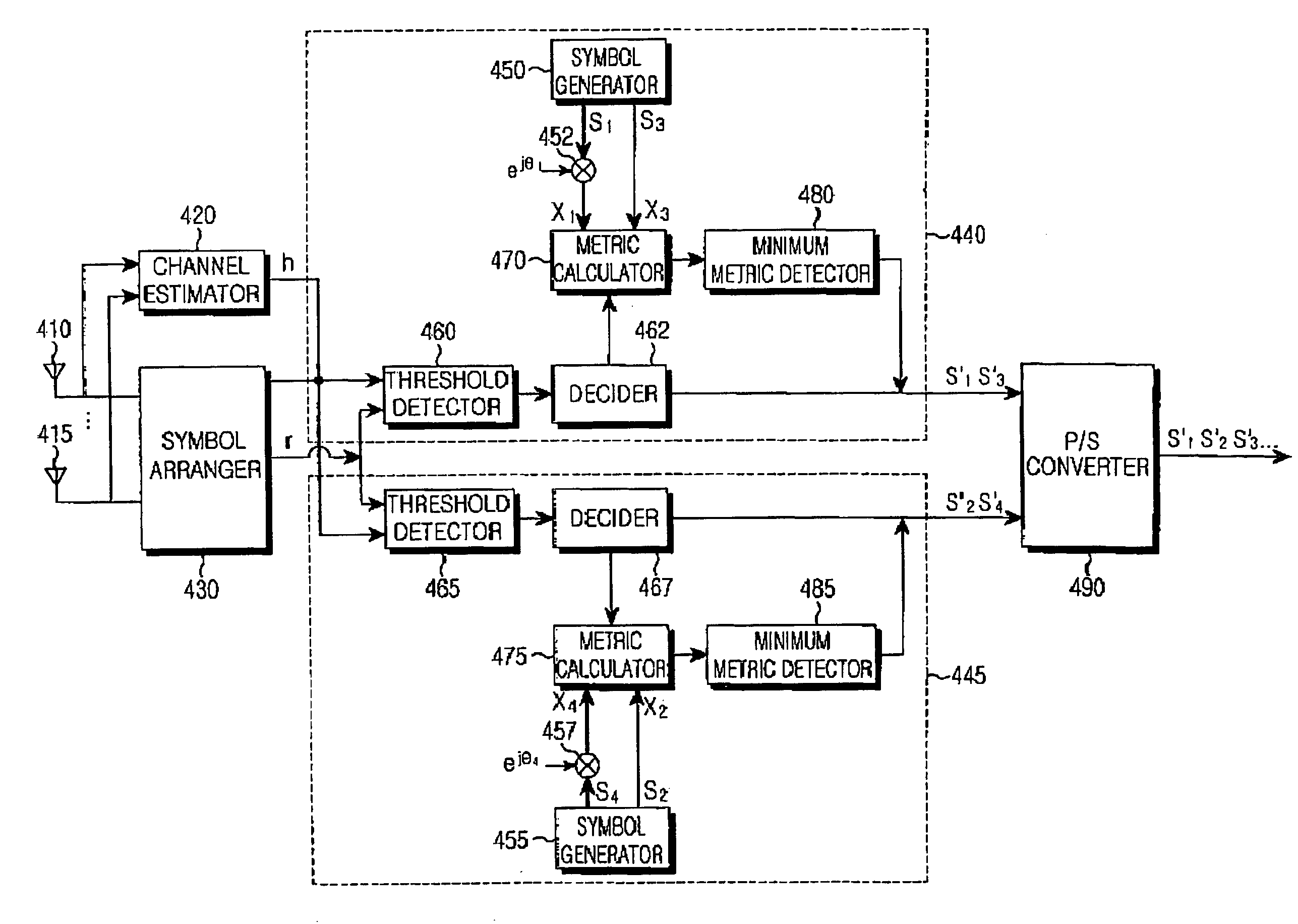
[0029]As is known, a receiver adopting ML (Maximum Likelihood) decoding computes metrics between a received signal and all possible symbols using channel estimates representing channel gains from transmitter antennas to receiver antennas, and detects a symbol giving a minimum metric.

[0030]Let a channel estimate from an ith transmitter antenna to a receiver antenna receiving the symbols of matrix (2) be hi. A metric for an arbitrary symbol set ct is computed as shown in formula (3):

[0031]∑t=14⁢⁢rt-∑i=13⁢⁢hi⁢ci2(3)

where rt is ...


PUM


Abstract

A receiver for receiving complex symbols in a radio communication system, in which a symbol arranger collects signals from at least three transmitter antennas through at least one receiver antenna over four time intervals; a channel estimator estimates at least three channel gains from the three transmitter antennas to the receiver antenna; first and second decoders each compute metrics for all possible pairs of symbols using the received signals and channel gains, and detect two symbols having a minimum metric; And a P/S (Parallel to Serial) converter arranges the detected symbols in the right order. Each decoder linearly operates the received signals and channel gains, pre-detects two symbols using threshold detection, and outputs the pre-detected symbols as final symbols if the product of the product of the pre-detected symbols and a constant determined by the channel gains is a minimum.

Description

PRIORITY[0001]This application claims priority under 35 U.S.C. § 119 to an application entitled “Receiving Apparatus in a Radio Communication System Using at Least Three Transmit Antennas” filed in the Korean Intellectual Property Office on Jan. 9, 2003 and assigned Ser. No. 2003-1456, the contents of which are herein incorporated by reference.BACKGROUND OF THE INVENTION[0002]1. Field of the Invention[0003]The present invention relates generally to a radio communication system, and in particular, to an apparatus using transmitter antenna diversity to combat fading-caused degradation.[0004]2. Description of the Related Art[0005]An effective technique of relieving multi-path fading in a radio communication system is time and frequency diversity. Vahid Tarokh et al. has proposed a space-time block code. Space-time block codes are a well-known antenna diversity scheme disclosed in “Space Time Block Coding from Orthogonal Design”, IEEE Trans. On Info., Theory, Vol. 45, pp. 1456-1467, Jul...

Claims


Application Information

Patent Timeline
Patent Type & Authority Patents(United States)
IPC IPC(8): H04B7/10H03M13/41H04B7/02H04B7/06H04B7/08H04B7/12H04J99/00H04L1/00H04L1/06
CPCH04L1/0618H04L1/0054H04B7/08
Inventor HWANG, CHAN-SOONAM, SEUNG-HOONKIM, YUNG-SOOCHUNG, JAE-HAK
Owner SAMSUNG ELECTRONICS CO LTD
Why Eureka
Try Eureka