
Subscriber Station for a Bus System, and Method for Increasing the Data Rate of a Bus System

a bus system and subscriber station technology, applied in the field of subscriber stations for bus systems, can solve the problems of affecting the reception of receivers, affecting the signal quality, and generating reflections in the transmission of data at each branch of the data line, so as to achieve the effect of increasing the data rate of the bus system

Active Publication Date: 2017-01-12
ROBERT BOSCH GMBH
View PDF2 Cites 4 Cited by
  • Summary
  • Abstract
  • Description
  • Claims
  • Application Information

AI Technical Summary

Benefits of technology

The present invention relates to a subscriber station for a bus system and a method that solves issues such as interference and reduced data rate. The subscriber station prevents signals from being destroyed and allows for a wider use of CAN-FD and higher data rates. It simplifies the design of the CAN network or bus system and increases the maximum transmittable data rate in CAN-FD. Additionally, it can be used to increase the data rate in a simpler manner by transmitting messages in a similar manner to other data transmission protocols. It is also advantageous in off-highway applications where more subscriber stations are connected to the bus line by different manufacturers.

Problems solved by technology

However, the problem is that reflections are produced in the transmission of data at each branch of the data lines.
These reflections are superimposed on the original signals and interfere with the reception by the receivers.
It is generally the case that the shorter the line between the interference source and the receiver and the longer the line between the transmitter and the receiver, the worse the signal quality.
As a result, the situation may occur in which the receiver could receive the signal without any errors, whereas a CAN subscriber station not involved in communication identifies an error and destroys the signal by an error message.
This results in the transmitter having to transmit the signal again, which unnecessarily increases the bus load on the CAN bus and unnecessarily slows down the transmission of data.
However, such protocols currently cannot be readily used.
Another problem is that the times at which one bit is intended to be sampled is set for each individual subscriber station when designing a CAN network or bus system.
In particular, when designing a network having a plurality of CAN-FD subscribers, it is difficult to set the times in such a manner that all subscribers can receive the signal without errors.

Method used


Image

  • Subscriber Station for a Bus System, and Method for Increasing the Data Rate of a Bus System
  • Subscriber Station for a Bus System, and Method for Increasing the Data Rate of a Bus System
  • Subscriber Station for a Bus System, and Method for Increasing the Data Rate of a Bus System

Examples


Embodiment Construction

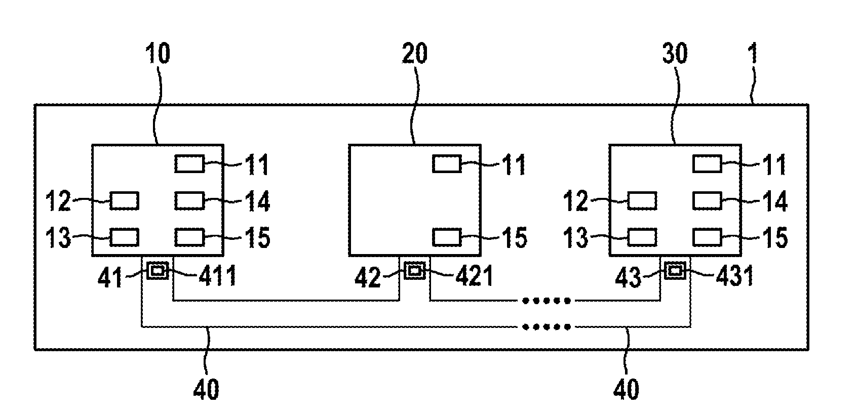
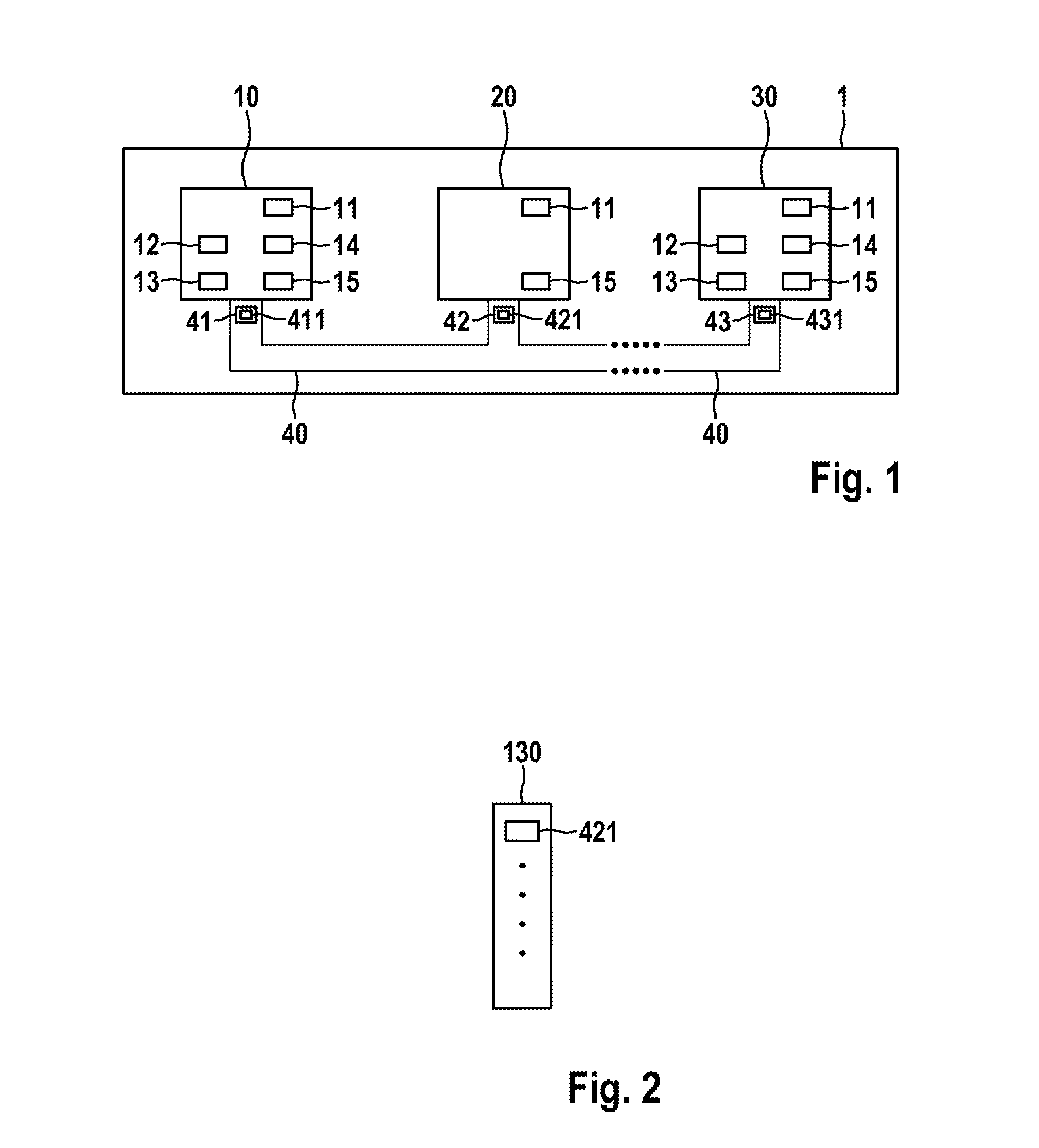
[0039]FIG. 1 shows a bus system 1 which may be, for example, a CAN bus system, a CAN-FD bus system, etc. The bus system 1 may be used in a vehicle, in particular a motor vehicle, an aircraft, etc., or in a hospital, etc.

[0040]In FIG. 1, the bus system 1 has a multiplicity of subscriber stations 10, 20, 30 which are each connected to a bus line 40. Messages 41, 42, 43 in the form of signals can be transmitted between the individual subscriber stations 10, 20, 30 via the bus line 40. The messages 41, 42, 43 each have one message identifier of message identifiers 411, 421, 431, which is also referred to as the CAN ID in CAN bus systems. The subscriber stations 10, 20, 30 may be, for example, control devices or display apparatuses or sensors of a motor vehicle.

[0041]As shown in FIG. 1, the subscriber station 10 has a communication control device 11, a checking device 12, a memory device 13, an error handling device 14 and a transmitting / receiving device 15. In contrast, the subscriber s...


PUM


Abstract

The disclosure relates to a participant station for a bus system and to a method for increasing the data rate of a bus system. The participant station comprises a device for receiving a message from at least one other participant station of the bus system via the bus system. In the bus system, an exclusive collision-free access of a participant station to a bus line of the bus system is ensured at least temporarily. The participant station also comprises a testing device for testing whether or not the received message is specified for the participant station and an error processing device for processing errors of the received message only when the test carried out by the testing device indicates that the received message is specified for the participant station.

Description

[0001]The present invention relates to a subscriber station for a bus system and to a method for increasing the data rate of a bus system, in which data transmission errors do not result in the transmission of data being terminated by subscriber stations which are not involved in the transmission of data.PRIOR ART[0002]For communication between sensors and control devices, the CAN bus system has found widespread acceptance. In the case of the CAN bus system, messages are transmitted using the CAN protocol, as described in the CAN specification in ISO11898. As the number of intelligent sensors increases and the control devices are networked more intensively in the vehicle, the number of subscriber stations on the CAN bus and the volume of data on the CAN bus are increasing more and more.[0003]DE10 000 305 A1 describes the CAN (Controller Area Network) and an extension of the CAN which is referred to as TTCAN (Time Trigger CAN). The media access control method used in the CAN is based...

Claims


Application Information

Patent Timeline
IPC IPC(8): G06F13/42G06F11/07
CPCG06F13/4282G06F11/0745G06F11/079H04L1/0053H04L1/0061H04L12/40032H04L43/0847H04L2001/0094H04L2012/40215H04L2012/40273
Inventor MACHAUER, RALFWEISSENMAYER, SIMON
Owner ROBERT BOSCH GMBH
Learn More