ATCA locking lever mounting structure

a technology of mounting structure and locking lever, which is applied in the direction of electrical apparatus construction details, furniture parts, and electrical apparatus casings/cabinets/drawers, etc., can solve the problems of locking lever a vibration and locking instability

Inactive Publication Date: 2007-11-27
ADLINK TECH INC
View PDF16 Cites 69 Cited by
  • Summary
  • Abstract
  • Description
  • Claims
  • Application Information

AI Technical Summary

Benefits of technology

[0011]According to another aspect of the present invention, the two locking levers are respectively pivotally provided at the tow sides of the motherboard blade for locking the motherboard blade to the machine case of the server system or unlocking the motherboard blade from the machine case of the server system conveniently without any tools.

Problems solved by technology

After insertion of the motherboard blade B in the machine case C of the server system, the locking lever A is biased to force a retaining portion A1 of the locking lever A into engage a part C1 of the machine case C and to touch a sensor switch B2, giving a signal indicative of positive positioning of the motherboard blade B. This locking lever mounting design has drawbacks as follows:1. The connection area between the locking lever A and the screw bolt A2 wears quickly with use, resulting in vibration of the locking lever A and locking instability.2. When the connection area between the locking lever A and the screw bolt A2 starts to wear, the locking lever A may be unable to trigger the sensor switch B2 accurately, resulting in operation abnormality of the motherboard blade B.

Method used


Image

  • ATCA locking lever mounting structure
  • ATCA locking lever mounting structure
  • ATCA locking lever mounting structure

Examples


Embodiment Construction

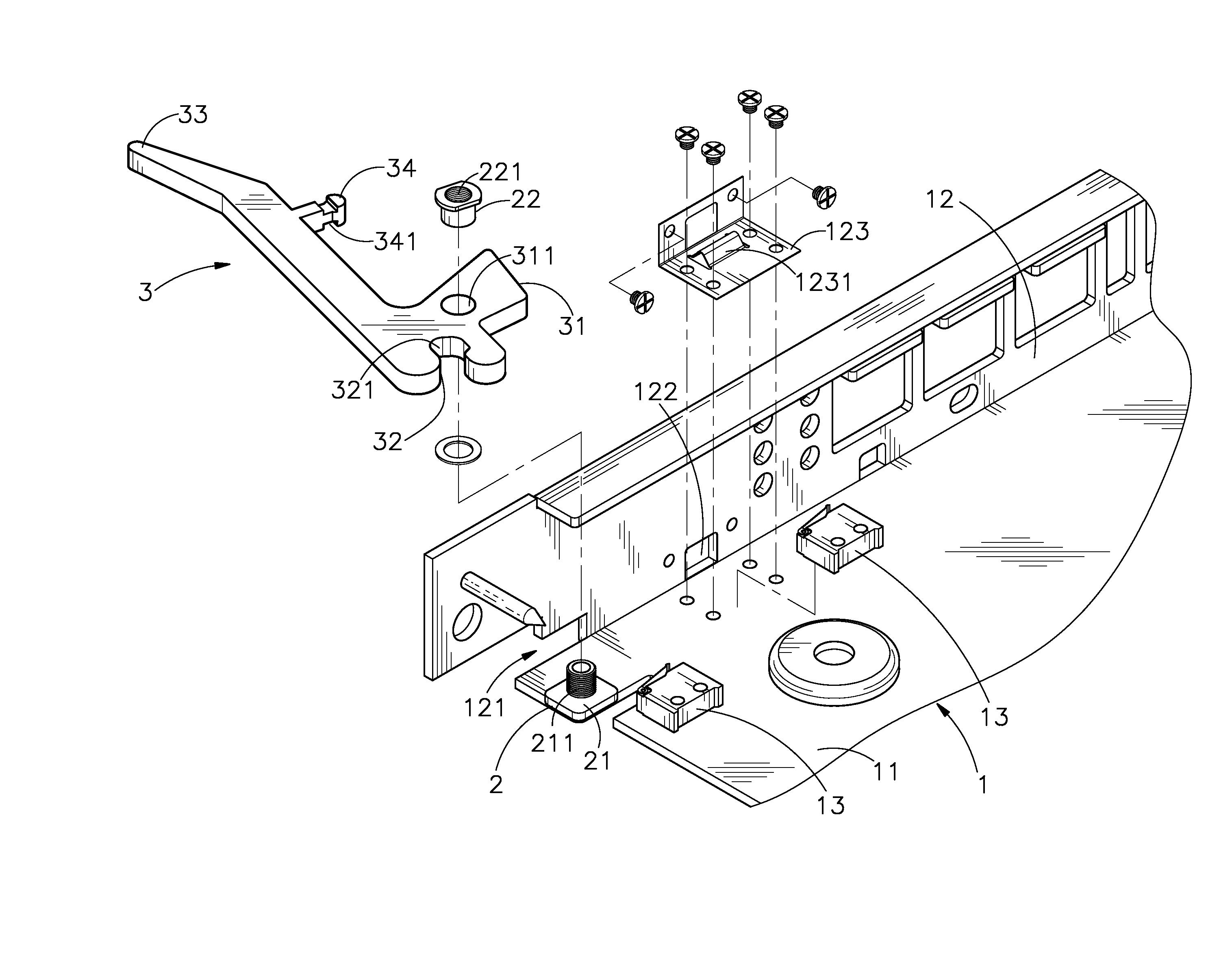
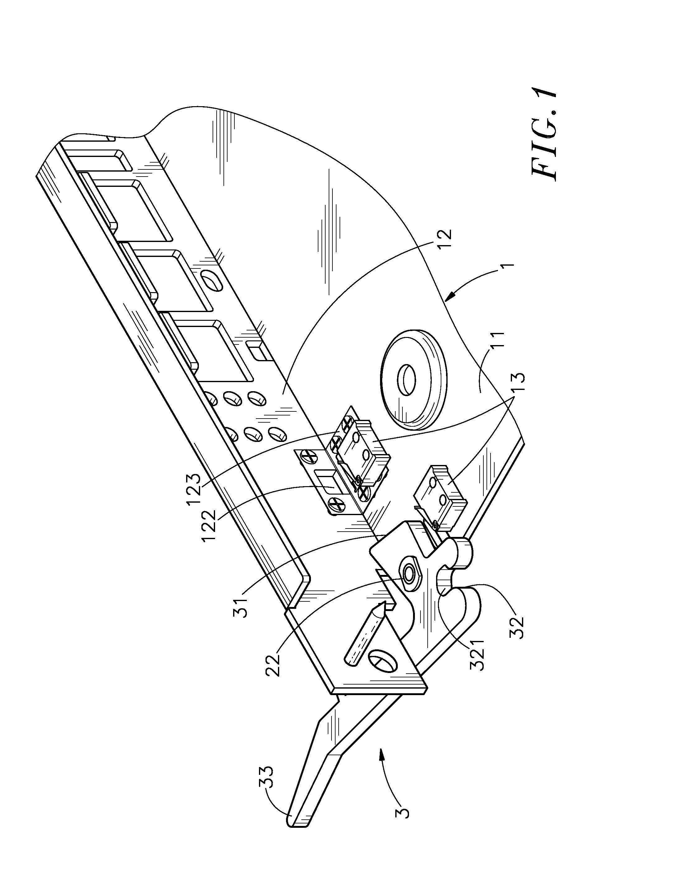
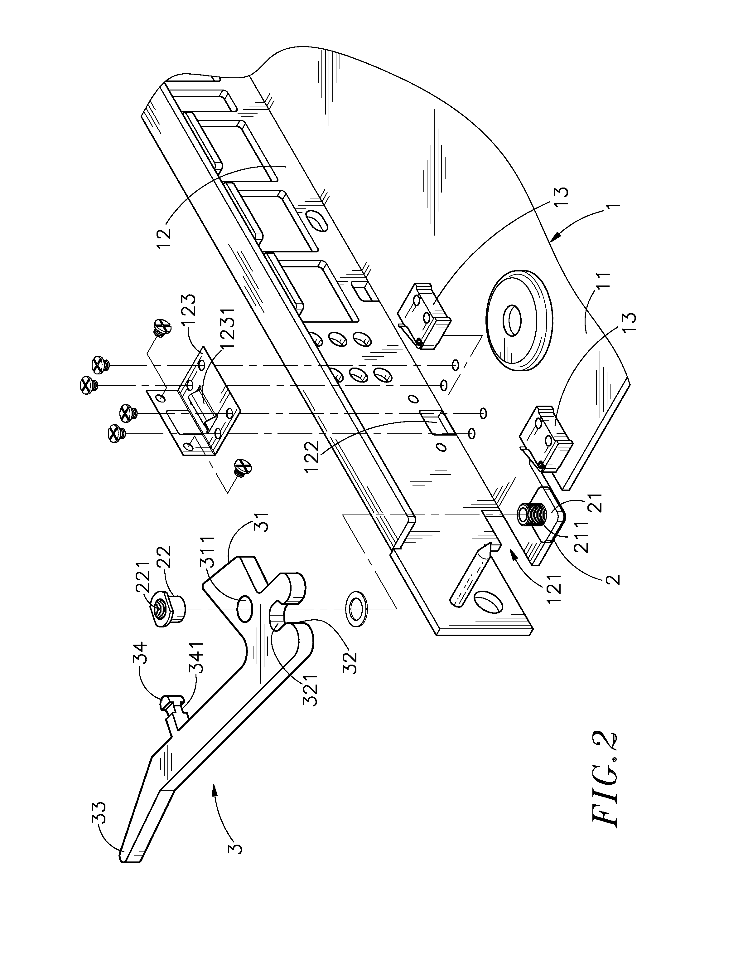
[0020]Referring to FIGS. 1˜3, an ATCA locking lever mounting structure in accordance with the present invention is shown comprising a motherboard blade 1, a pivot device 2, and a locking lever 3.

[0021]The motherboard blade 1 comprises a motherboard 11, which has electronic component parts arranged thereon, a face panel 12, which is provided at one side of the motherboard 11, and at least one, for example, two sensor switches 13, which are mounted on the motherboard 11. The face panel 12 has an end notch 121 at one end thereof adjacent to the motherboard 11, and a through hole 122 near but spaced from the end notch 121 at a distance. A grounding plate 123 is fastened to the abutted area between the motherboard 11 and the face panel 12 corresponding to the through hole 122. The grounding plate 123 has a retaining protrusion 1231.

[0022]The pivot device 2 has a mounting base 21 fixedly mounted on the motherboard 11 near the end notch 121 of the face panel 12, a screw rod 211 perpendicul...


PUM


Abstract

An ATCA locking lever mounting structure installed in a motherboard blade formed of a motherboard and a face panel and inserted into a machine case of a server system is disclosed to included a grounding plate fixedly provided at the motherboard near a through hole on the face panel, and a locking lever pivoted to a pivot device at the motherboard and turnable about the pivot device between the locking position where the locking lever locks the motherboard blade to the machine case of the server system and connects the grounding plate to the machine case to have the motherboard be grounded, and the unlocking position where the motherboard blade is unlocked from the machine case.

Description

BACKGROUND OF THE INVENTION[0001]1. Field of the Invention[0002]The present invention relates to blade servers and more specifically, to an ATCA locking mounting structure for enabling a motherboard blade to be locked to a machine case of a server system and electrically connected to the server system quickly without any tools.[0003]2. Description of the Related Art[0004]Currently, many enterprises install relatively cheaper mini servers to satisfy network traffic requirements. In order to improve further economic effect, blade servers are developed. A blade server is essentially a housing for a number of individual minimally-packaged computer motherboard “blades”, each including one or more processors, computer memory, computer storage, and computer network connections, but sharing the common power supply and air-cooling resources of the chassis. The idea is that by placing many blades in a single chassis, and then 19-inch rack-mounting them, systems can be more compact and powerfu...

Claims


Application Information

Patent Timeline
Patent Type & Authority Patents(United States)
IPC IPC(8): H05K7/10
CPCH05K7/1487H05K7/1409
Inventor FANG, CHIH-LIANG
Owner ADLINK TECH INC
Why Eureka
Try Eureka