Cross-path calibration for data acquisition using multiple digitizing paths

a data acquisition and digitizing path technology, applied in the field of high dynamic range measurement method and system, can solve the problems of not being able to achieve the optimal range, affecting the accuracy of data acquisition, and difficult to get all input ranges to their suitable value, etc., to achieve accurate and reliable measurements, reduce or complete elimination of input range settings, and achieve accurate voltage measurement

Active Publication Date: 2007-11-27
CRYSTAL INSTR CORP
View PDF7 Cites 23 Cited by
  • Summary
  • Abstract
  • Description
  • Claims
  • Application Information

AI Technical Summary

Benefits of technology

[0005]The present invention utilizes multiple A / D (analog-to-digital) paths and cross-path calibration to provide accurate and reliable measurements for each input channel in a data acquisition system. When the system and method are applied, user and automated methods of selecting among a number of alternative input range settings can be reduced, or even eliminated. That is, there is a significant reduction or complete elimination of input range settings in a measurement system in accordance with the invention. As an analogy, when using a conventional voltage meter, a user must select the “best” input voltage range setting in order to achieve the most accurate voltage measurement. The voltage meter may be capable of providing measurements from a few millivolts to 500 volts, but the accuracy will depend upon the selection of the subsets of ranges within this overall range. In comparison, the system in accordance with the invention eliminates the selection of subsets.
[0010]When addressing the concerns, the values that are of greatest importance are those at transition measurement points when the final data stream transitions from one path to another path during the “stitching” process. Without proper treatment, there will be discontinuities at the transitions. A conventional calibration process can be applied to the measurement channel of the data acquisition to reduce the absolute gain and offset errors. However, this will not solve the problems. Alternatively, in the publication “New Technology Increases the Dynamic Ranges of Data Acquisition Systems Based on 24-Bit Technology” (cited above), it is suggested to build very accurate front end circuitry, which is usually very expensive. Therefore, the present invention uses a special cross-path calibration process. It is not necessary that the cross-path calibration eliminate, or even reduce, the absolute measurement error of measurement paths. Instead, the calibration is designed to match the errors among the different paths, so that the paths will generate the measurement values as close as possible. This will allow the transition of the signal from one region to another to be very smooth during the “stitching” process.

Problems solved by technology

Users are often troubled by being unable to set the optimum range because the measured signal either is non-stationary or has an unknown amplitude.
For a high channel count system having multiple relevant input ranges, it is even more difficult to get all the input ranges to their suitable value.
For non-stationary signals such as electricity transients, auto-ranging usually does not work because each pulse may take a different magnitude.
For a signal with long time history and a large range of amplitude change, auto-ranging cannot be applied at all, because during the measurement procedure it is not allowed to change the input range, i.e., the amplifier gain setting.

Method used


Image

  • Cross-path calibration for data acquisition using multiple digitizing paths
  • Cross-path calibration for data acquisition using multiple digitizing paths
  • Cross-path calibration for data acquisition using multiple digitizing paths

Examples


case 2

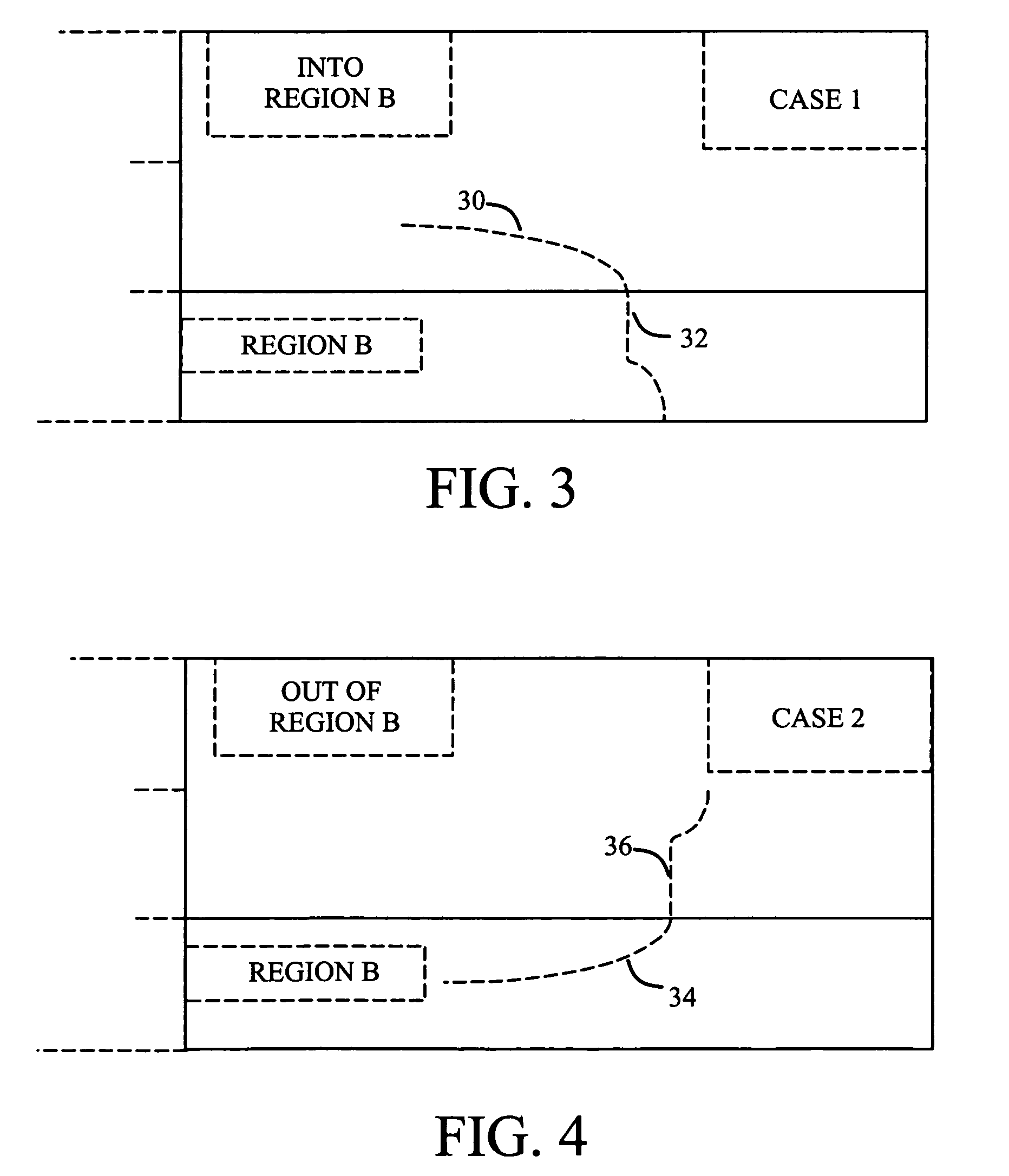
[0039]Case 2 shows that the signal is first in Region B, then it rises to “Out of Region B”. Using the method described above, when the signal is in Region B, Ka and Ba are estimated. Then, Ka and Ba are used to calculate Ya, once they enter the “Out of Region B”. This can be done in real-time while data is being acquired.

case 1

[0040]Case 1 is more complicated than Case 2, because the data points that are used to estimate Ka and Ba occur after the transition. The cross-channel calibration adjustment must be applied to the HISTORICAL data series, i.e., the old data. This can be done because data has been acquired. The software can retrieve data to the extent necessary to re-apply the Ka and Ba to the data that has been acquired.

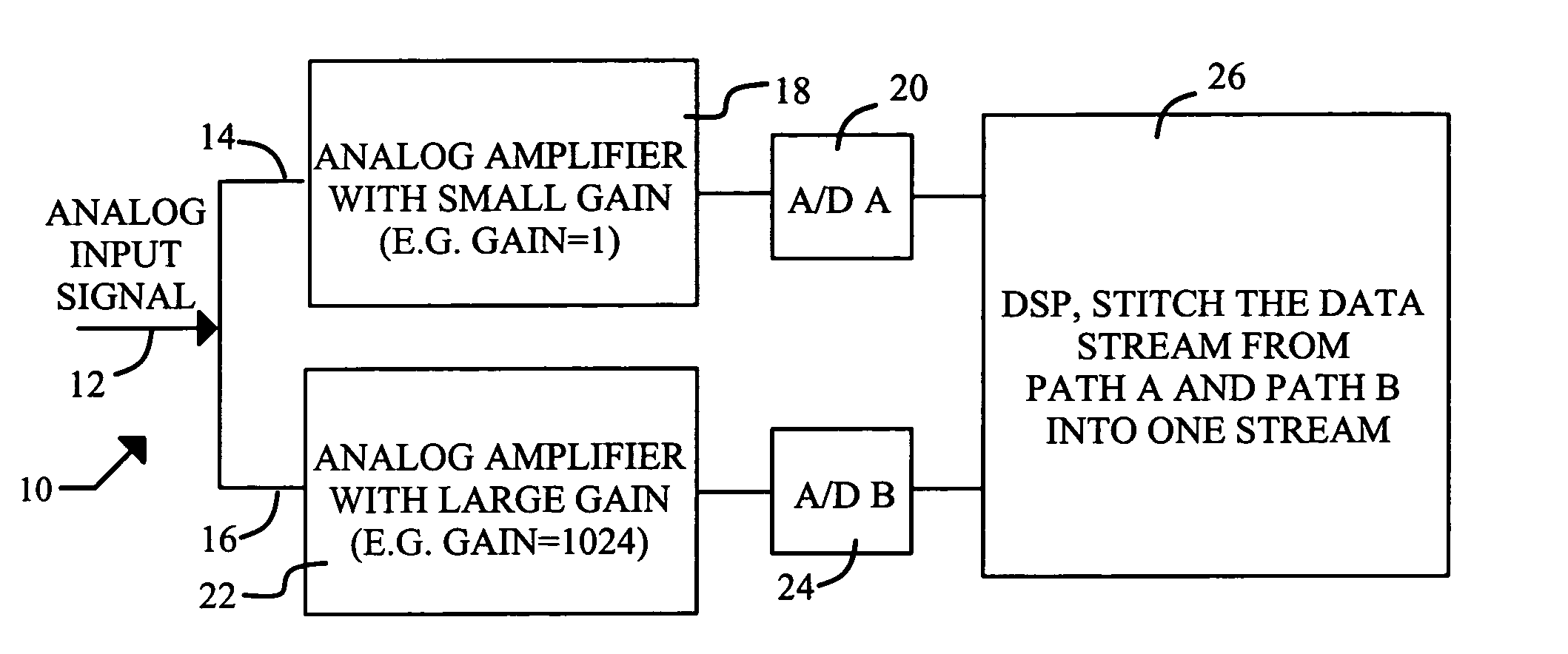
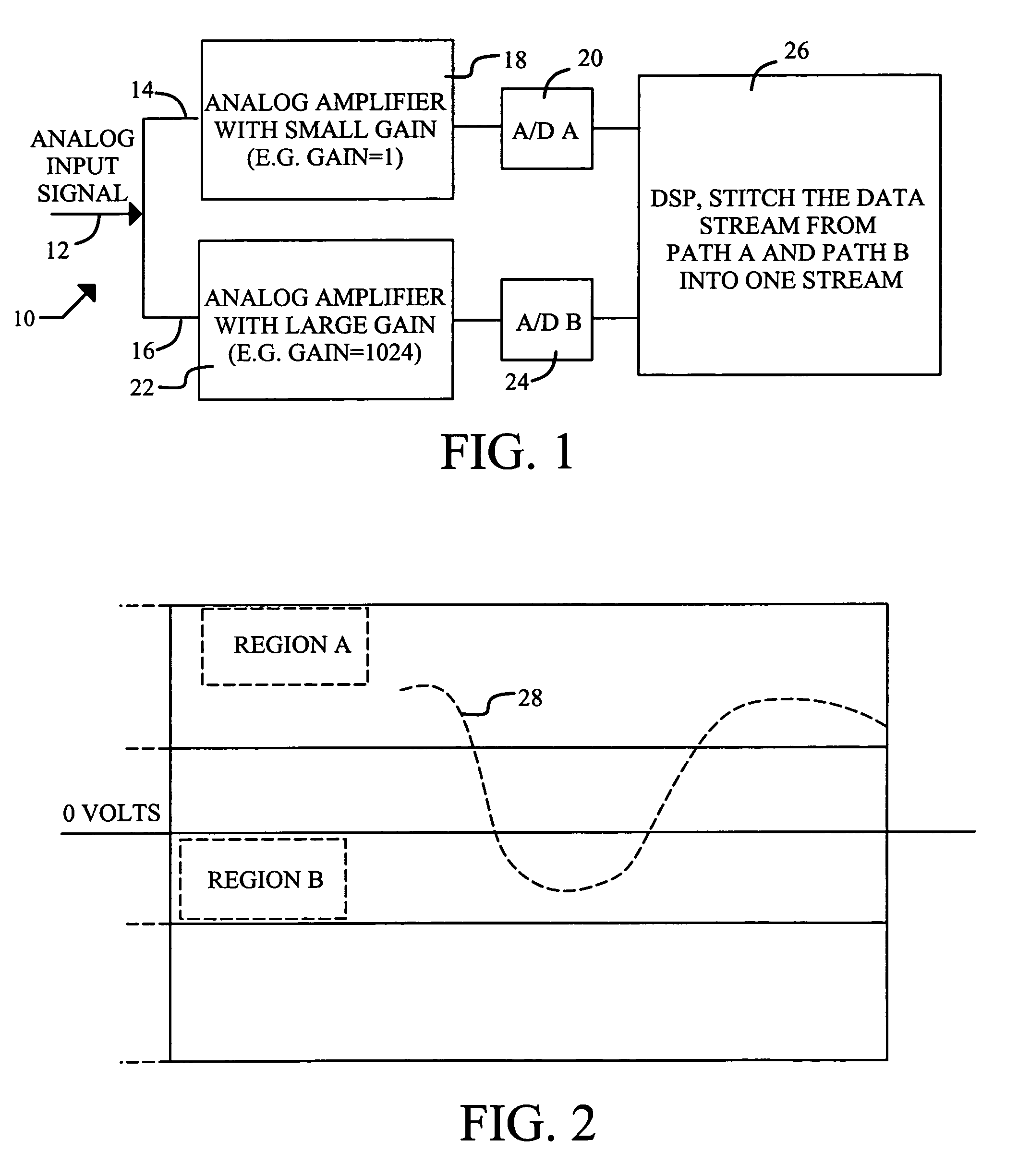
[0041]The previous discussion uses a measurement channel with two A / D paths as an example. The concept can be expanded to measurement systems which employ more than two A / D paths. Regardless of the number of paths, the cross-calibration method uses the measurement values in the paths with smaller input ranges (i.e., larger gains) to calibrate the data values from the paths with larger input ranges (i.e., with smaller gains). FIG. 8 shows this expansion of the invention to include three A / D paths, with each path having an ADC 54, 56 and 58 and an amplifier 60, 62 and 64 with a unique ...


PUM


Abstract

The present invention utilizes multiple A / D (analog-to-digital) paths and cross-path calibration to provide accurate and reliable measurements for each input channel in a data acquisition system. When the system and method are applied, user and automated methods of selecting among a number of alternative input range settings can be reduced, or even eliminated. That is, there is a significant reduction or complete elimination of input range settings in a measurement system. For each measurement channel of interest, the input signal is directed to at least two paths, e.g., Path A and Path B. The first path measures the full range (e.g., + / −10 volts), while the second path includes a high-gain amplifier. Each path includes an analog-to-digital converter (ADC), so that there is a one-to-one correspondence between the number of paths and the number of ADCs, which sample the input signal simultaneously.

Description

TECHNICAL FIELD[0001]The invention relates generally to high dynamic range measurement method and system, and more particularly to high dynamic range measurement for a data acquisition system.BACKGROUND ART[0002]In a conventional measurement system, the input range setting is one of the most important settings. For example, in an analysis system there may be a number of different input voltage range settings for each input channel. The input range setting has a direct impact on the quality of measurement, which is mainly reflected by SNR (Signal-to-Noise Ratio) or dynamic range. Users are often troubled by being unable to set the optimum range because the measured signal either is non-stationary or has an unknown amplitude. For a high channel count system having multiple relevant input ranges, it is even more difficult to get all the input ranges to their suitable value. To deal with this situation, many instruments are designed with an intelligent auto-ranging capability. “Auto-ran...

Claims


Application Information

Patent Timeline
Patent Type & Authority Patents(United States)
IPC IPC(8): G01D18/00
CPCG01D18/00G01D3/02
Inventor ZHUGE, JAMES
Owner CRYSTAL INSTR CORP
Why Eureka
Try Eureka