
Hands-free toilet and urinal flushing device

a flushing device and toilet technology, applied in mechanical control devices, process and machine control, instruments, etc., can solve the problems of prone to malfunction, high system cost, and widespread use of public toilets

Inactive Publication Date: 2007-12-04
BHATT HARIN G +2
View PDF4 Cites 10 Cited by
  • Summary
  • Abstract
  • Description
  • Claims
  • Application Information

AI Technical Summary

Problems solved by technology

The pervasive use of public toilets is becoming a major health issue with the possible transmission of serious diseases such as HIV, hepatitis, etc. by the undesirable hand contact with bacteria from a toilet handle.
These systems are quite expensive and prone to malfunction.

Method used


Image

  • Hands-free toilet and urinal flushing device
  • Hands-free toilet and urinal flushing device
  • Hands-free toilet and urinal flushing device

Examples


Embodiment Construction

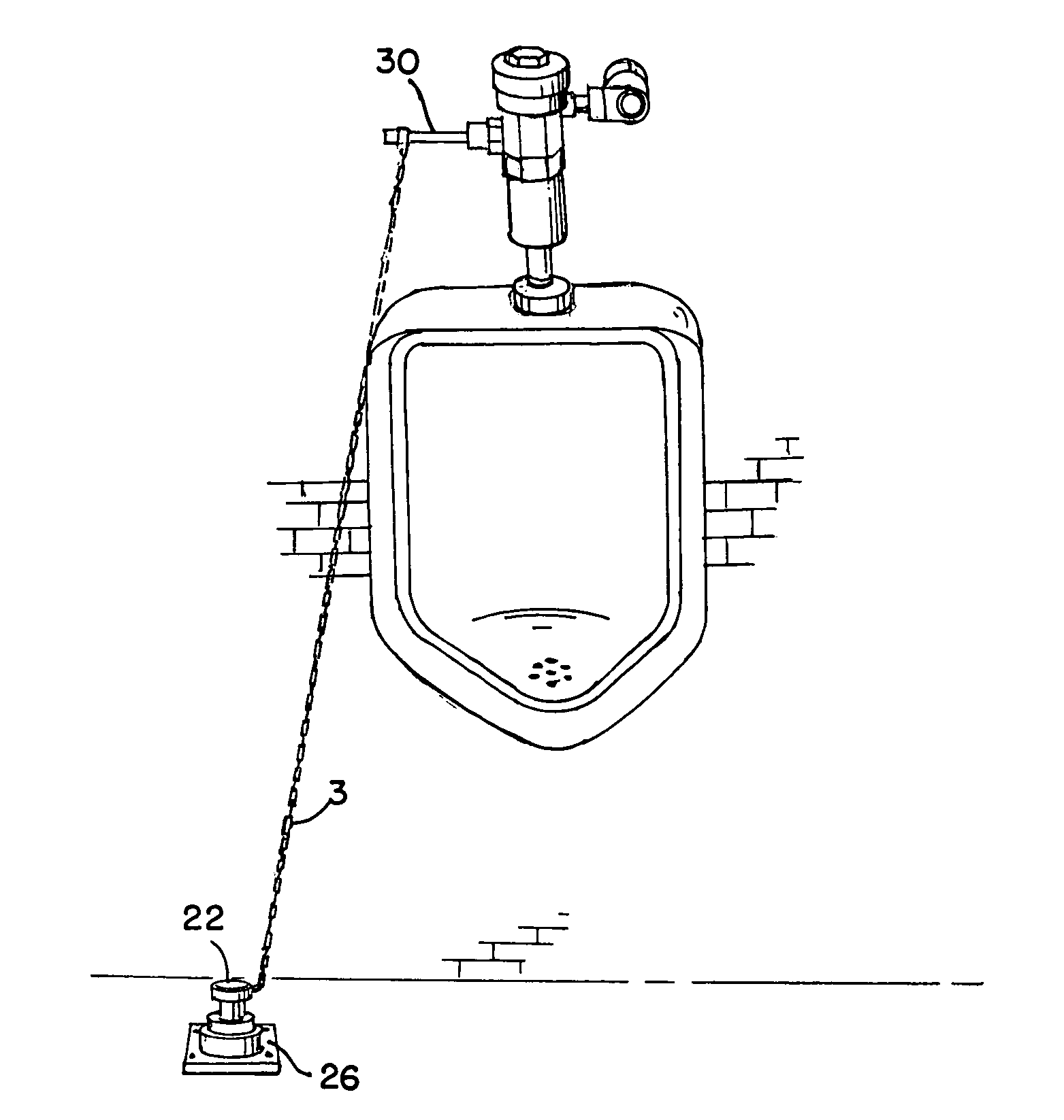
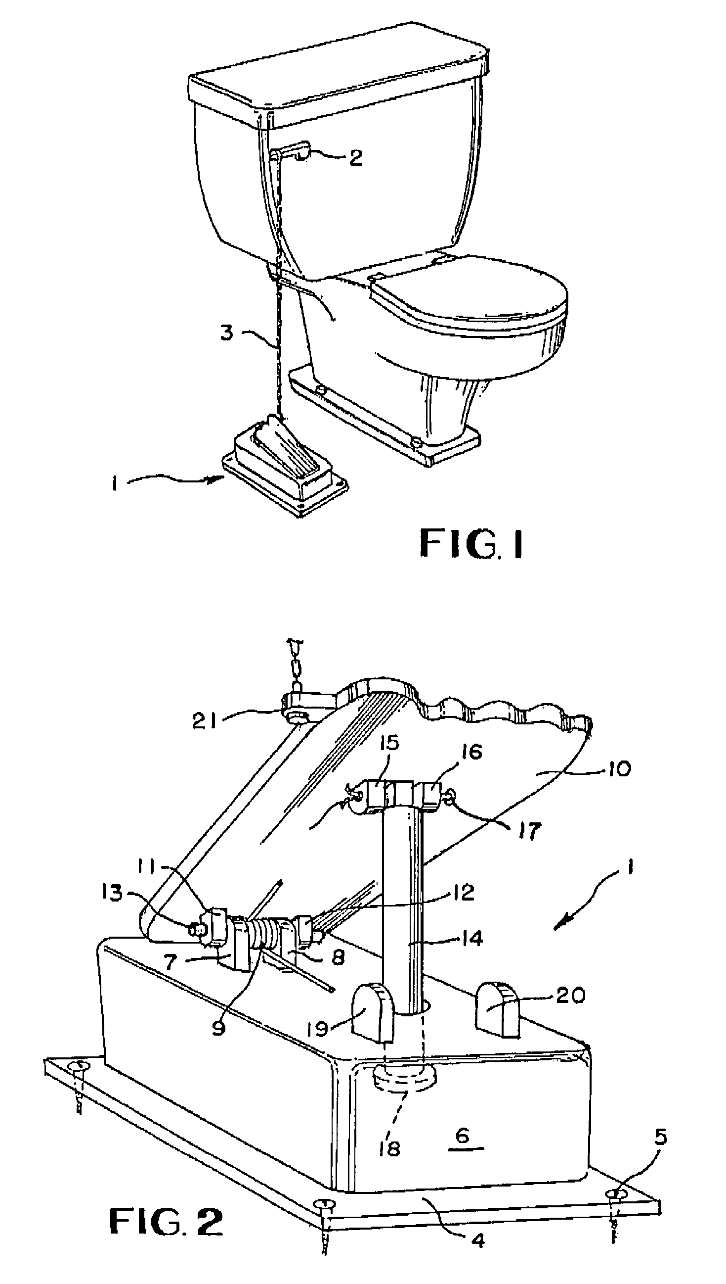
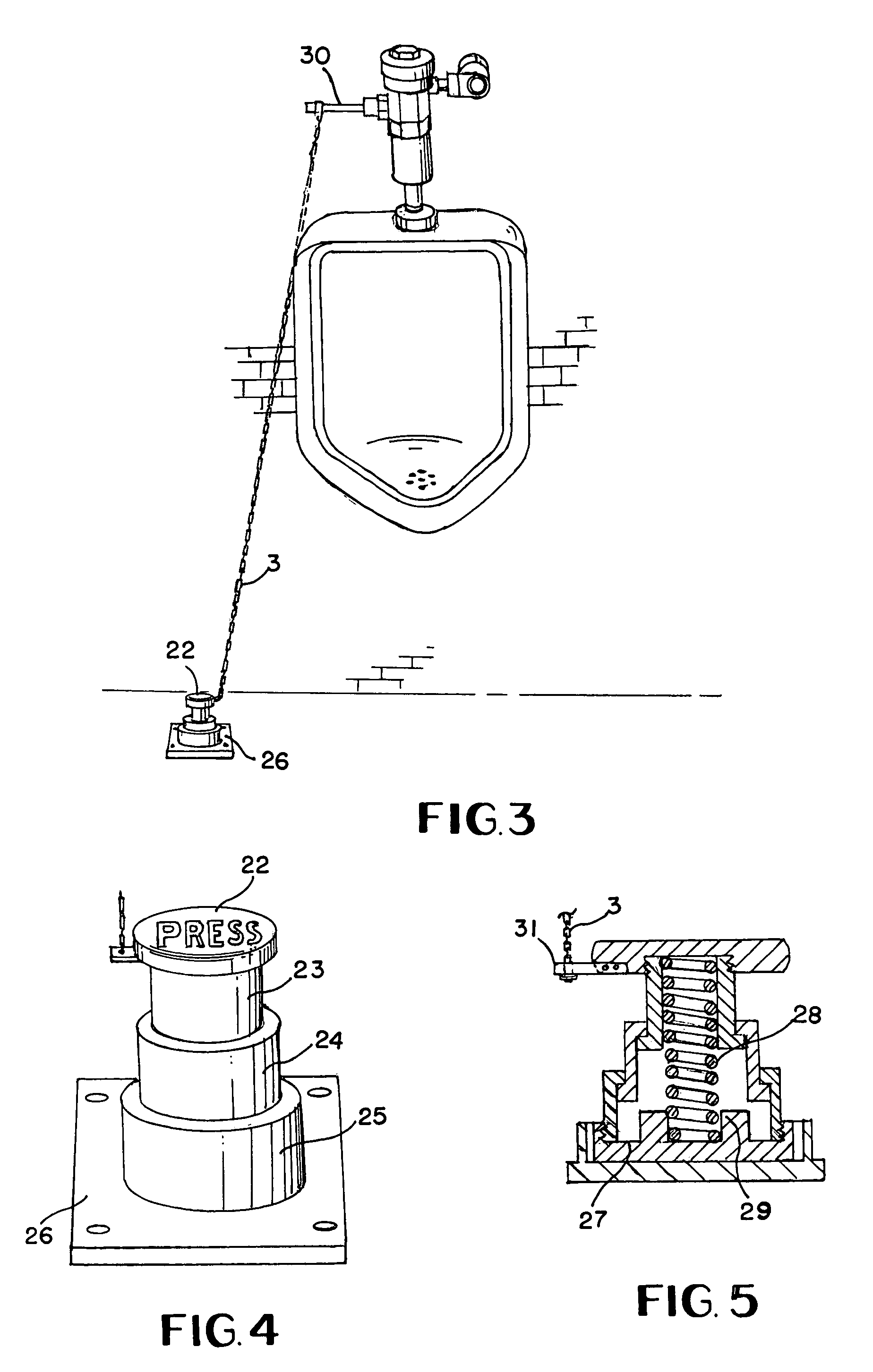
[0009]In the drawings and with particular reference to FIG. 1, the flushing device according to this invention is indicated generally by the numeral 1 and which is attached to conventional toilet handle 2 by means of chain 3. In FIG. 2, flushing device 1 is shown and includes base plate 4 which is securable to the floor by means of multiple screws 5. Cover 6 is disposed on base plate 4 with studs 7 and 8 upstanding therefrom. In addition, V-type compression spring 9 is disposed between studs 7 and 8. Reciprocating pedal 10 is attached at one end to cover 6 by means of studs 11 and 12 which are secured to the bottom surface of pedal 10. Studs 7 and 8 are interconnected to studs 11 and 12 by means of rivet 13 which extends through apertures in studs 7, 8, 11 and 12 and through the center of spring 9, as shown in FIG. 2.

[0010]For the purpose of stabilizing pedal 10, rod 14 is secured to foot pedal 10 remote from spring 9 by means of studs 15 and 16 which are attached to the bottom surf...


PUM


Abstract

A toilet and urinal flushing device comprising a reciprocating pedal attached to a toilet handle with the pedal being reciprocated by means of a spring.

Description

BACKGROUND OF THE INVENTION[0001]The pervasive use of public toilets is becoming a major health issue with the possible transmission of serious diseases such as HIV, hepatitis, etc. by the undesirable hand contact with bacteria from a toilet handle. There are several different types of modern hands-free flushing systems including sound-activated, infrared, and photosensor flush activation technologies. These systems are quite expensive and prone to malfunction.BRIEF SUMMARY OF THE INVENTION[0002]According to this invention, a toilet and urinal flushing device comprises a reciprocating pedal attached to a toilet handle with the pedal being reciprocated by means of a compression spring. Activation is achieved by pressing downwardly on the pedal so as to rotate the handle to initiate a flushing operation.BRIEF DESCRIPTION OF THE SEVERAL VIEWS OF THE DRAWINGS[0003]In the drawings,[0004]FIG. 1 is a perspective view of the flushing device according to this invention;[0005]FIG. 2 is an enl...

Claims


Application Information

Patent Timeline
IPC IPC(8): E03D5/00
CPCE03D5/08G05G1/42G05G1/30Y10T74/20528
Inventor BHATT, HARIN G.BHATT, GARGI H.BHATT, PARASHAR H.
Owner BHATT HARIN G
Learn More