Illumination apparatus and video projection display system

a technology of video projection and illumination apparatus, which is applied in the field of illumination apparatus and video projection display system, can solve the problems of low heat dissipation ability of heat dissipation, high probability, and inability to tolerate temperature rise in led arrays

Inactive Publication Date: 2007-12-04
SANYO ELECTRIC CO LTD
View PDF5 Cites 103 Cited by
  • Summary
  • Abstract
  • Description
  • Claims
  • Application Information

AI Technical Summary

Benefits of technology

[0008]In view of the problems residing in the prior art, it is an object of the present invention to provide a video projection display system that enables to achieve balance between the light amount of projected light, and heat releasing effect of a light source, and an illumination apparatus for use in the video projection display system.

Problems solved by technology

Furthermore, since the lens elements 33 are arrayed close to each other substantially without clearance, the LED devices 31 corresponding to these lens elements 33 are resultantly arranged close to each other, which may lower heat releasing ability of dissipated heat.
If the heat releasing ability of dissipated heat of the LED array is lowered, it is highly likely that temperature rise in the LED array is intolerable.
Such a phenomenon may obstruct miniaturization of the illumination apparatus and the video projection display system.

Method used


Image

  • Illumination apparatus and video projection display system
  • Illumination apparatus and video projection display system
  • Illumination apparatus and video projection display system

Examples


Embodiment Construction

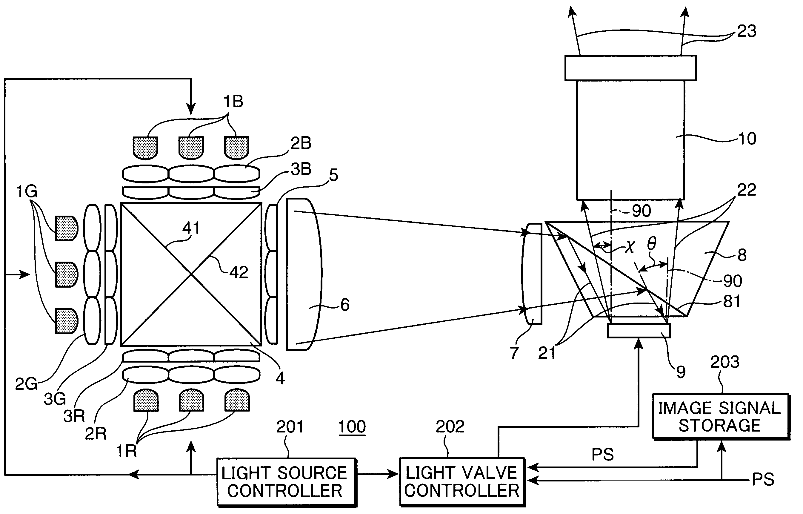
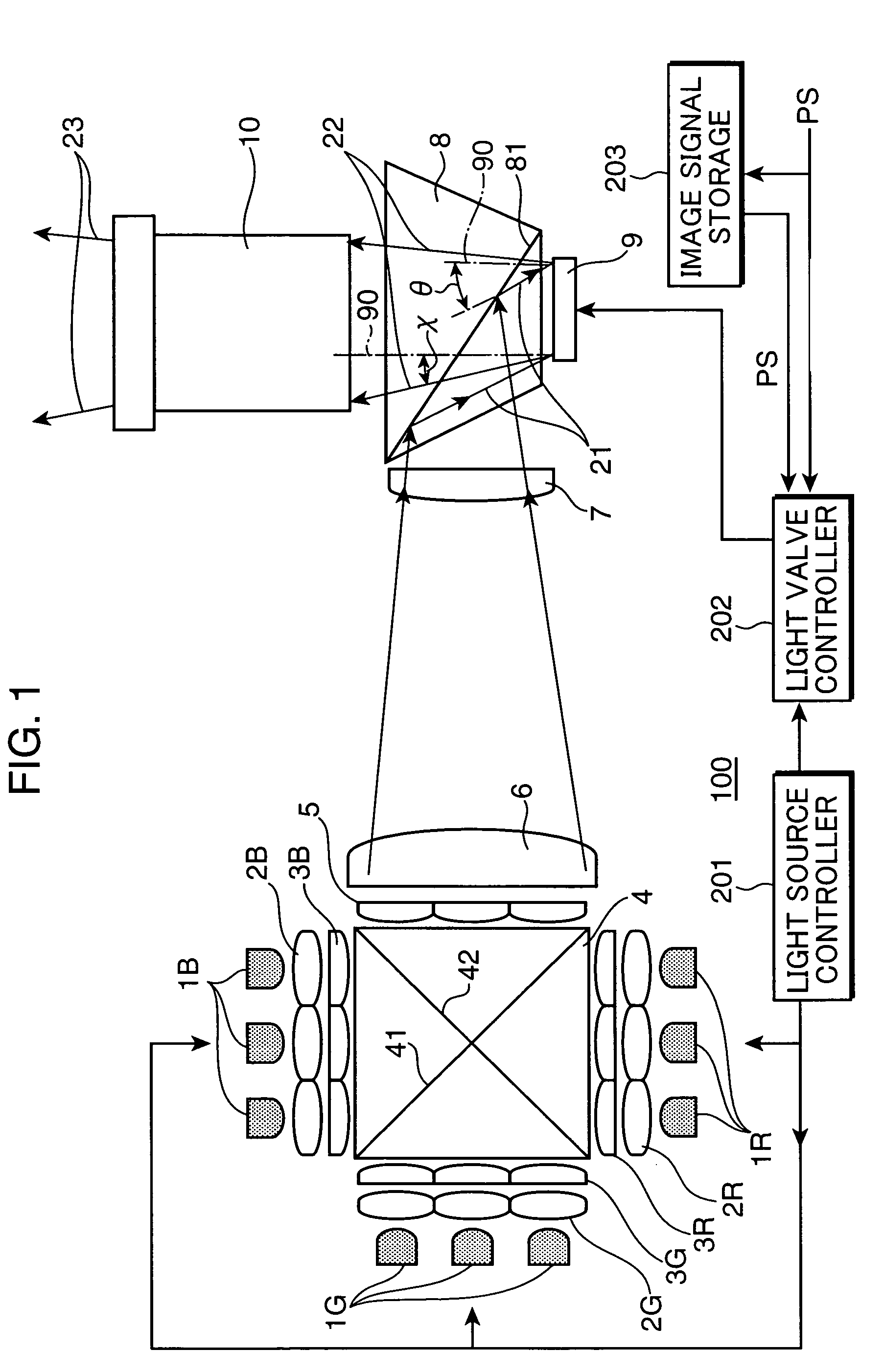
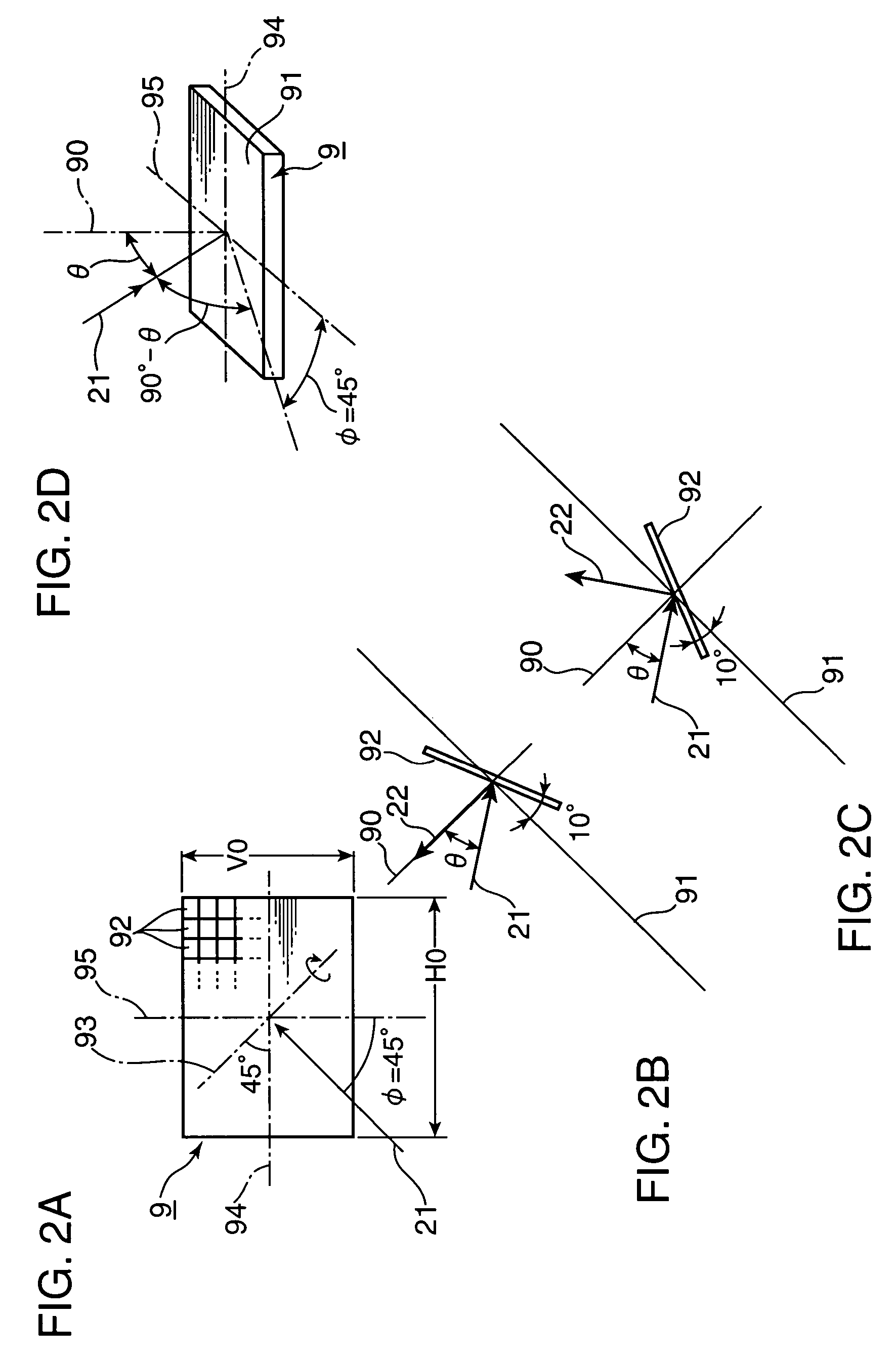
[0018]FIG. 1 is an illustration showing primary components of a video projection display system embodying the invention. The video projection display system 100 comprises light emitting diode (LED) arrays 1R, 1G, and 1B, condenser lens groups 2R, 2G, and 2B, first fly-eye lenses 3R, 3G, and 3B, a dichroic prism 4, a second fly-eye lens 5, a first condenser lens 6, a second condenser lens 7, a TIR prism 8, a digital micro mirror device (DMD) 9, a projection lens 10, a light source controller 201, a light valve controller 202, and an image signal storage 203.

[0019]The entirety or each of the LED arrays 1R, 1G, and 1B corresponds to an example of a light source of the invention. Further, in the case where the entirety of the LED arrays 1R, 1G, and 1B serves as an example of the light source of the invention, the LED arrays 1R, 1G, and 1B correspond to a first light source, a second light source, and a third light source of the invention, respectively. Further, the condenser lens groups...


PUM


Abstract

An illumination apparatus includes: a group of light source segments; a group of condenser lenses arrayed as opposed to the group of light source segments, and a group of rectangular lens elements arrayed as opposed to the group of condenser lenses for converging a light ray transmitted through the opposing condenser lens; and an illumination optical system for guiding the rays to an illumination plane. The lens elements have a shape of a rectangle and are arrayed in a rectangular effective area in such a way that a longitudinal axis of each lens elements intersects an axis passing a side of the effective area at 45°.

Description

BACKGROUND OF THE INVENTION[0001]1. Field of the Invention[0002]The present invention relates to a video projection display system of projecting and displaying a light image which has been obtained by modulating projected light, and an illumination apparatus for use in the video projection display system.[0003]2. Description of the Related Art[0004]There has been known a video projection display system of projecting and displaying, onto a screen or a like apparatus, a light image which has been obtained by modulating light rays from a light source based on an image signal pixel by pixel (e.g., in Japanese Unexamined Patent Publication No. 10-123512). The video projection display system disclosed in the publication employs a liquid crystal display (LCD) device, which is a light transmissive device, as a device (called as “light valve”) which modulates incident light from a light source. Further, the video projection display system uses an LED array comprised of a multitude of light e...

Claims


Application Information

Patent Timeline
Patent Type & Authority Patents(United States)
IPC IPC(8): G03B21/26B60Q1/26F21V9/00G03B21/20G03B21/28G03B21/14F21V1/00G02B3/00G02B27/09G02B27/14G03B21/00H04N3/08H04N5/74H04N9/31
CPCG02B3/0056G02B27/0961G02B27/1033G02B19/0028H04N9/315H04N9/3197G02B19/0066G02B27/149
Inventor IKEDA, TAKASHIARAI, KAZUHIRO
Owner SANYO ELECTRIC CO LTD
Why Eureka
Try Eureka