Thermal imager utilizing improved radiometric calibration technique

Active Publication Date: 2007-12-04
RAYTEK
View PDF25 Cites 35 Cited by
  • Summary
  • Abstract
  • Description
  • Claims
  • Application Information

AI Technical Summary

Benefits of technology

[0004]According to one aspect, the present invention provides a thermal imaging apparatus comprising a thermal image camera having a lens and a display. The camera further includes a focal plane array located behind the lens for converting imaging radiation to produce an image signal for further processing. A shutter mechanism is operative to selectively inhibit expo

Problems solved by technology

Although FPAs provide good imagery of the scene, it is much more difficult to use an FPA imager to accurately measure the temperature of objects in the scene.
It is believed t

Method used


Image

  • Thermal imager utilizing improved radiometric calibration technique
  • Thermal imager utilizing improved radiometric calibration technique
  • Thermal imager utilizing improved radiometric calibration technique

Examples


Embodiment Construction

[0020]It is to be understood by one of ordinary skill in the art that the present discussion is a description of exemplary embodiments only, and is not intended as limiting the broader aspects of the present invention, which broader aspects are embodied in the exemplary constructions.

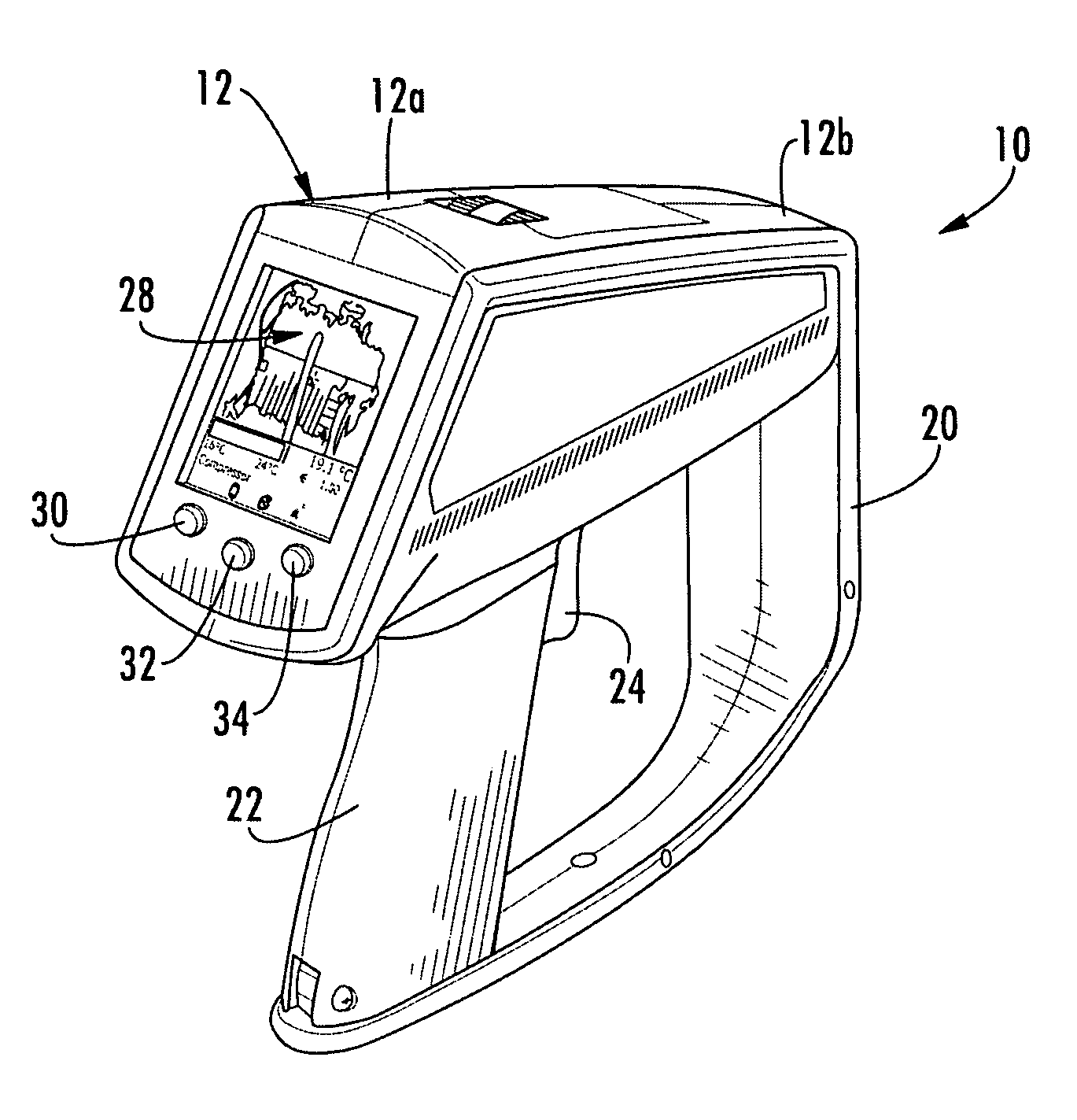
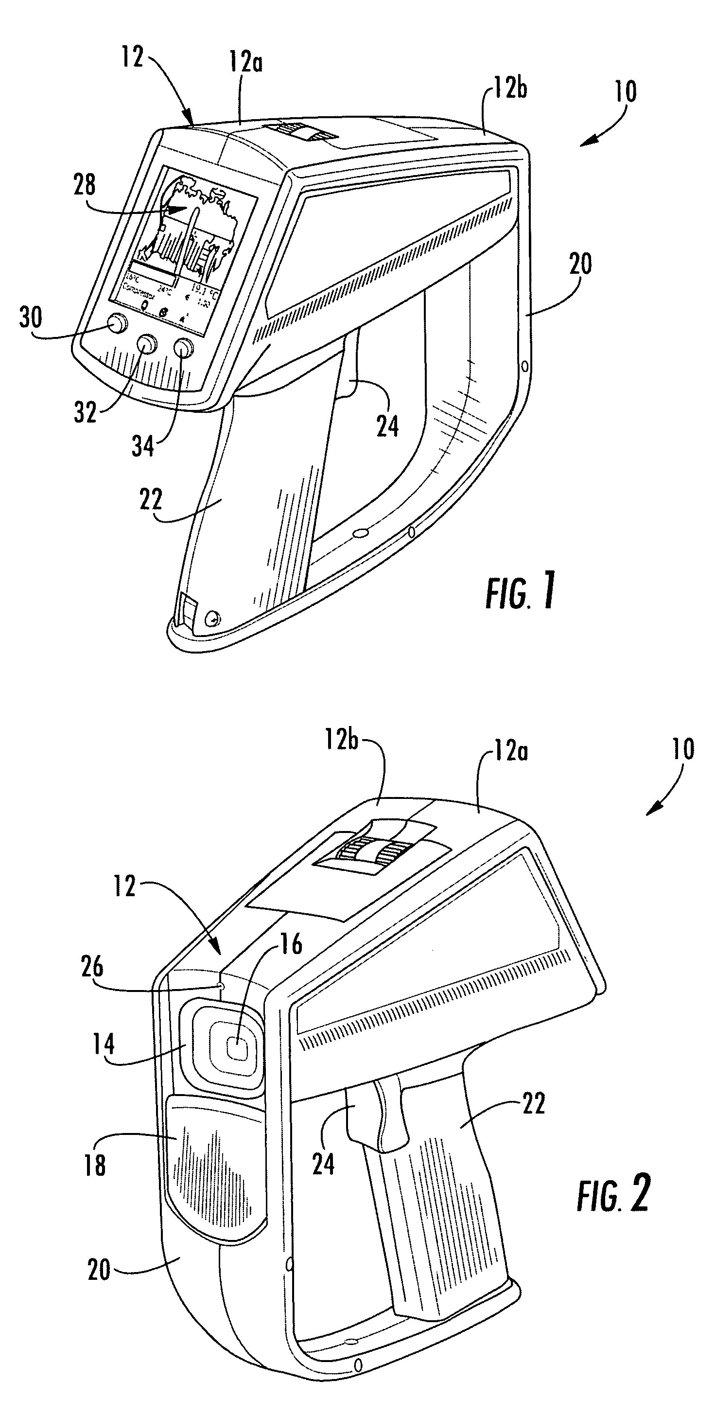
[0021]FIGS. 1 and 2 illustrate a thermal imager 10 constructed in accordance with the present invention. Imager 10 includes a housing 12 in which the components of a thermal image camera are located. Preferably, housing 12 is formed by complementary left and right housing portions 12a and 12b which are joined together during assembly. While any suitable material can be utilized, housing portions 12a and 12b are preferably formed of a rigid high impact plastic material. Selected regions of housing 12 may be desirably overmolded with a softer polymeric material.

[0022]As shown in FIG. 2, housing 12 includes a front portion enclosing a hood 14 behind which the device's lens 16 is located. One skilled in the...


PUM


Abstract

A thermal imaging apparatus comprises a thermal image camera having a lens and a display. The camera further includes a focal plane array located behind the lens for converting imaging radiation to produce an image signal for further processing. A shutter mechanism is operative to selectively inhibit exposure of the focal plane array to the imaging radiation such that the focal plane array produces a reference signal. Processing circuitry is operative to receive the image signal and produce a corresponding thermal image on the display. The processing circuitry is further operative to utilize the image signal and the reference signal to derive temperature information.

Description

BACKGROUND OF THE INVENTION[0001]The present invention relates generally to thermal imagers. More particularly, the invention relates to a thermal imager that utilizes an improved technique to calibrate a focal plane array so as to provide accurate radiometric information.[0002]Thermal imaging cameras are used in a wide variety of applications, such as predictive maintenance in industrial facilities. While past imagers often utilized a scanning technique, modern imagers generally incorporate an infrared (IR) focal plane array (FPA) for producing the thermal image. FPAs have many advantages, such as the speed at which successive images can be produced for display.[0003]Although FPAs provide good imagery of the scene, it is much more difficult to use an FPA imager to accurately measure the temperature of objects in the scene. It is believed that others have provided radiometers employing FPAs, but these devices have required complicated cooling or temperature stabilization mechanisms ...

Claims


Application Information

Patent Timeline
IPC IPC(8): G12B13/00
CPCG01J5/522H04N5/33G01J2005/0077G01J5/53
Inventor KING, STEPHEN R.HEINKE, THOMASCARLSON, PAUL S.WARNKE, STEFAN H.
Owner RAYTEK
Why Eureka
Try Eureka