Method and apparatus for compensating for fixed pattern noise in an imaging system

a fixed pattern noise and imaging system technology, applied in the field of image signal processing, can solve the problems of limiting the precision of correction, the setup method involving exposure to a dark frame is susceptible to measurement clipping, and the multiplicative component cannot be determined

Inactive Publication Date: 2007-12-04
HAND HELD PRODS
View PDF173 Cites 49 Cited by
  • Summary
  • Abstract
  • Description
  • Claims
  • Application Information

AI Technical Summary

Problems solved by technology

Fixed pattern noise refers to inconsistencies in the responsiveness of an image sensor output that results from sensor characteristics or properties affecting pixels of the sensor in the same way each time data is captured from those pixels.
Various problems have been noted in prior art imaging systems configured for fixed pattern noise compensation, both in set up routine methods for configuring an imaging system for fixed pattern noise compensation, and in methods for compensating pixel values read from a pixel array.
This method can be employed to estimate an additive component of fixed pattern noise, but cannot be used to determine a multiplicative component of fixed pattern noise.
Furthermore, the setup method involving exposure to a dark frame is susceptible to measurement clipping.
A major problem with this scheme is that values read from the array can be corrected only to a small number of discrete voltages, thereby limiting the precision of the correction.
Also, this scheme requires additional hardware.
Failure to compensate adequately for fixed pattern noise has significant consequences, for example, when an imaging system is employed in indicia decoding applications.
Fixed pattern noise has been observed to cause a symbology decoding apparatus to misplace edge positions, and to result in erroneous identification of edge positions.
The likelihood of an erroneous edge position identification increases when a decoding apparatus is employed to captured symbols having higher densities.

Method used


Image

  • Method and apparatus for compensating for fixed pattern noise in an imaging system
  • Method and apparatus for compensating for fixed pattern noise in an imaging system
  • Method and apparatus for compensating for fixed pattern noise in an imaging system

Examples


Embodiment Construction

[0022]There is described a pixel value adjustment method and apparatus. In one embodiment, pixel values can be adjusted by execution of an algorithm for adjusting pixel values. In one embodiment, an apparatus capable of executing an algorithm for adjusting pixel values is capable of operating in a decoding operating application. In one embodiment, an apparatus capable of executing an algorithm for adjusting pixel value is capable of operating in a video display operating application.

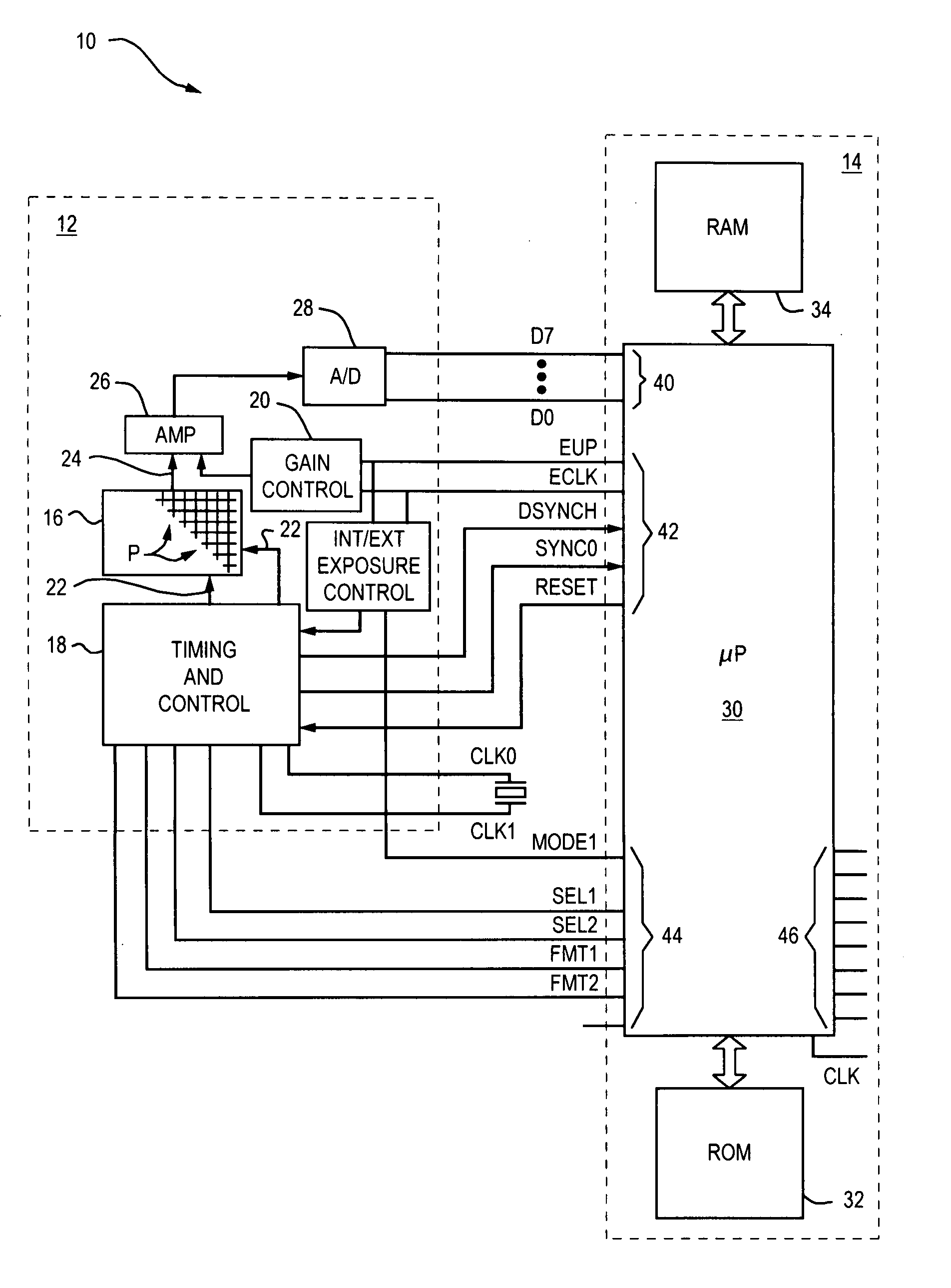
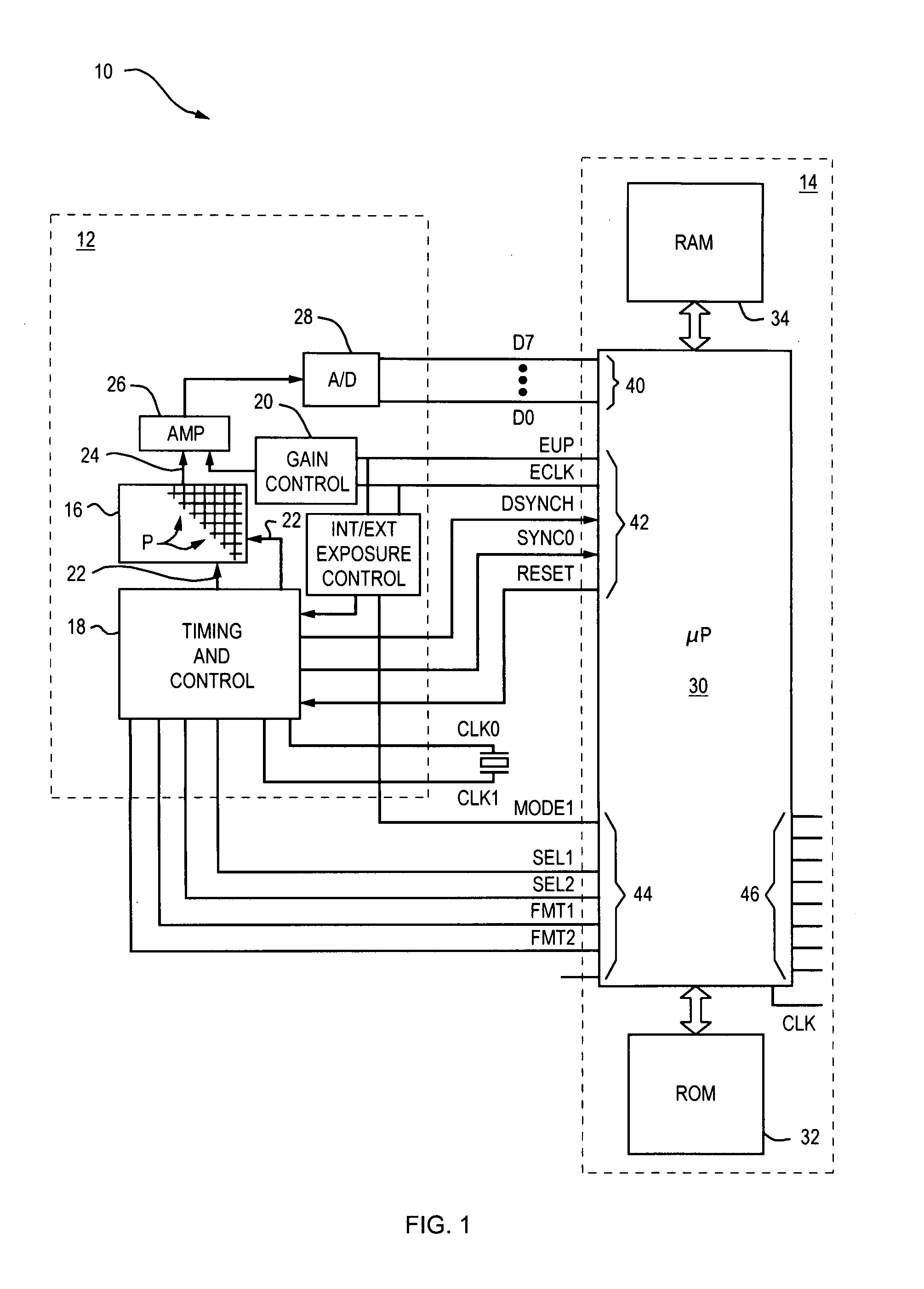
[0023]The invention relates to a method and apparatus for configuring an imaging system to compensate for fixed pattern noise, variations in pixel values captured from an image sensor that vary according to a fixed pattern. In a method for configuring an imaging system for compensating an additive term component of fixed pattern noise, a pixel array is exposed to a scene of known radiance and an average white value is determined for each pixel of an array. Each average white value is compared to a predet...


PUM


Abstract

There is described a pixel value adjustment method and apparatus. In one embodiment, pixel values can be adjusted by execution of an algorithm for adjusting pixel values. In one embodiment, an apparatus capable of executing an algorithm for adjusting pixel values is capable of operating in a decoding operating application. In one embodiment, an apparatus capable of executing an algorithm for adjusting pixel values is capable of operating in a video display operating application.

Description

BACKGROUND OF THE INVENTION[0001]1. Field of the Invention[0002]The invention relates generally to image signal processing and in particular to a method and apparatus for adjusting pixel values.[0003]2. Background of the Prior Art[0004]When pixel values, representative of pixel voltages are read from an image sensor pixel array, slight inconsistencies are observable between the voltages of the various pixels even when the array is exposed to a scene of uniform radiance. The inconsistency in the pixel values read from the various pixels is commonly referred to as “noise” either of a fixed pattern noise type or a random noise type.[0005]Fixed pattern noise refers to inconsistencies in the responsiveness of an image sensor output that results from sensor characteristics or properties affecting pixels of the sensor in the same way each time data is captured from those pixels. Random, or stochastic noise refers to inconsistencies which vary each time data is captured from the pixels.[000...

Claims


Application Information

Patent Timeline
Patent Type & Authority Patents(United States)
IPC IPC(8): H04N5/217G06K7/10G06K9/00H04N5/365H04N5/369
CPCH04N5/2176H04N5/3651H04N5/76H04N5/2173H04N5/3658H04N25/63H04N25/671H04N25/677H04N25/60
Inventor HUSSEY, ROBERT M.HAVENS, WILLIAM H.
Owner HAND HELD PRODS
Why Eureka
Try Eureka